A simple kit for students to gain insight into field poles, armatures and switches, one mounting base, two coils of insulated wire , field pole, mounting bracket, two armature halves, one piece of insulating tubing, motor shaft, two commutator insulators, two bronze wire brushes, two shaft supports, four paper fasteners, a AA battery holder and 6 each of screws and nuts.
Requires one AA battery, not supplied, with assembly instructions.
For Westminster Electromagnetic Kit giving 1 V full wave rectified DC and 1 V / 2 V AC outputs at 8 A max.
The circuit diagram is printed on the top panel which also carries mains switch, light indicator and output sockets for DC and AC With 1.5 meter mains detachable cable.
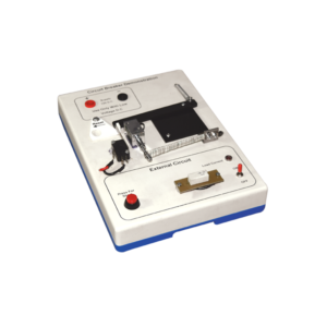
Investigate the working principle of circuit breaker type fuse with this demonstration model.
The apparatus is built on a robust plastic base and includes resistive loads to simulate external wiring circuits.
Applications of the thermal response of bimetal strips and also electromagnetism (movement from a solenoid) are clearly demonstrated in this model.
When a 12 V DC supply is connected (not supplied) the LED lights to show that current is flowing in the external circuit and the bi-metal strip can be seen to bend as its heater coil raises the temperature.
After a few minutes the bending is sufficient to trip the mechanism and the current path is broken.
At any current selection a short circuit situation can be initiated by pressing the red button and this produces an immediate response from the solenoid to disconnect the supply.
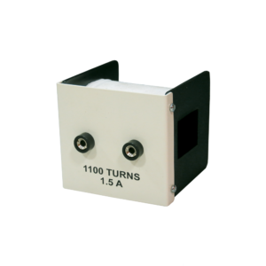
For use on double 'C' core, wound with 1,100 turns of 22 swg copper wire with a resistance of about 6 ohms and inductance of about 15 henries, size 100 x 60 x 55 mm approx.
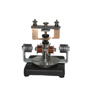
The motor consists of a two pole armature mounted between the ends of two bar magnets.
The armature has a two section commutator and a pair of slip-rings on its shaft and is so constructed that the wire cannot slip off the iron core.
The upper bearing and brushes for the commutator are mounted on a strong upright.
Separate brushes are provided for the commutator and for slip rings and each are connected to a terminal.
The magnets are held in position by thumb screws.
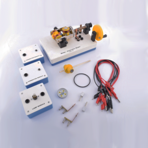
This motor-generator set gives students an insight into the physical and technical relationships on which electric motors, generators and transformers are based.
The modular system allows to set up different function models without tools: Various DC motors Series and shunt motor Synchronous motor DC generator and alternator Transformer.
This set allows the performance of 10 student experiments about the following topics:
Magnetic field of a coil
Conversion of electrical energy into kinetic energy
Commutator
Direct current motor
Synchronous motor
Series and shunt-wound motors
Electromagnetic induction
The electrical generator
Engine-generator
Transformer
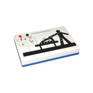
This apparatus is an effective demonstration of how the earth wire and fuse act together to protect both the user and the appliance.
When the appliance is connected correctly and the LEDs in the appliance will illuminate to show the appliance is working.
A fault is then demonstrated by swapping the live wire from inside the appliance to the case to show either the fuse melts (protecting the user and appliance) or in the case of no earth wire, the LEDs illuminate to indicate the passage of current through the person to ground.
The fuse is easily visible and can be seen to ‘blow’ when a fault occurs.The unit is supplied with 10 m of fuse wire and full instructions.
A 12 V DC power supply is required.
Connections are made via 4 mm shrouded sockets.


































Reviews
There are no reviews yet.