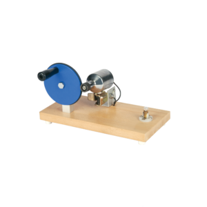
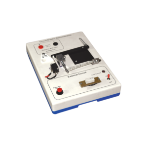
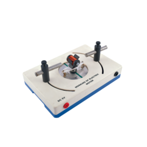
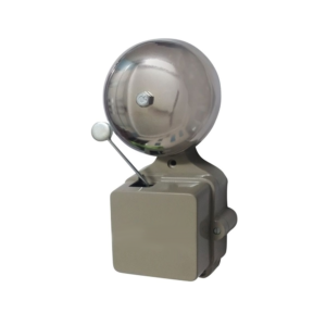
With this simple electric motor model students can investigate the relationship between voltage supplied to rotor and polarity / position of magnets.
On applying 6V DC to 4mm sockets, the rotor will begin to rotate across its vertical axis.
For Westminster Electromagnetic Kit giving 1 V full wave rectified DC and 1 V / 2 V AC outputs at 8 A max.
The circuit diagram is printed on the top panel which also carries mains switch, light indicator and output sockets for DC and AC With 1.5 meter mains detachable cable.
Wound on rectangular bobbin, for use with 220 – 240 V AC mains with detachable mains connector with moulded plug, A 4 mm socket is provided for earthing.
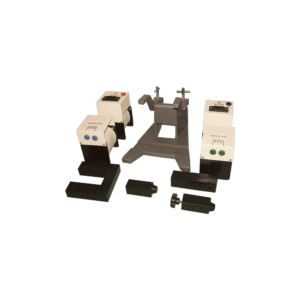
This motor-generator set gives students an insight into the physical and technical relationships on which electric motors, generators and transformers are based.
The modular system allows to set up different function models without tools: Various DC motors Series and shunt motor Synchronous motor DC generator and alternator Transformer.
This set allows the performance of 10 student experiments about the following topics:
Magnetic field of a coil
Conversion of electrical energy into kinetic energy
Commutator
Direct current motor
Synchronous motor
Series and shunt-wound motors
Electromagnetic induction
The electrical generator
Engine-generator
Transformer
The large size of this battery operated apparatus allows students to better understand the operation of this basic circuit.
Works on 9 V Battery.
Includes Instructions.

On wooden stand.
The motor consists of a two pole armature mounted between the ends of two bar magnets.
The armature has a two section commutator and a pair of slip-rings on its shaft and is so constructed that the wire cannot slip off the iron core.
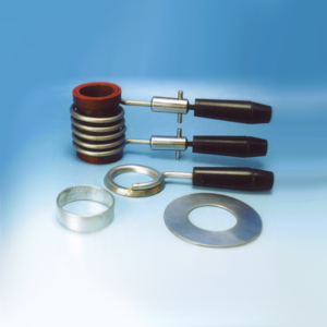
The upper bearing and brushes for the commutator are mounted on a strong upright.
Separate brushes are provided for the commutator and for slip rings and each are connected to a terminal.
The magnets are held in position by thumb screws.
Reviews
There are no reviews yet.