Error: Contact form not found.
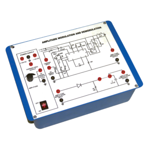
Amplitude Modulation And Demodulation
Instrument is design to demonstrate the method to transmit signals via. Electromagnetic transmission. It is still used in radio system to transmit audio signal although it has lesser in popularity compared to FM (Frequency Modulation) due to its lower signal to noise ratio.
Technical Specification :-
1. I C based DC regulated Power Supply ±12 V / 500 mA.
2. Audio frequency 1 KHz / 0-2 Vpp for modulating signal 455 KHz / 2.5 Vpp approx. for Carrier Frequency.
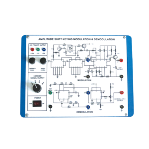
Amplitude Shift Keying Modulation And Demodulation
This Instrument is design to demonstrate the method to transmit signals via. Electromagnetic transmission and to study the Amplitude shift keying Modulation and Demodulation. Whole instrument is placed in plastic moulded box and 2 mm banana plug leads are provided for modulation and demodulation connections.
Technical Specification:-
1. Fixed Output DC Regulated Power Supply of ±12 V, +5 V.
2. 100KHz with 5 Vpp amplitude (Approx.) for carrier frequency.
3. In built square wave data generator.
4. Circuit diagrams for Modulator and Demodulator are printed on the milky white top panel.
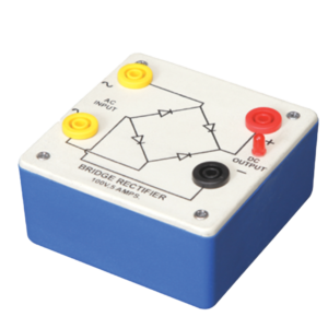
Bridge Rectifier
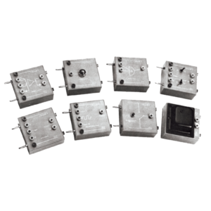
Bridge Rectifier is made of four diodes connected in a bridge circuit. It is housed in a plastic moulded box. This bridge rectifier converts alternating current (AC) into direct current (DC). It provides the same output polarity for either input polarity. All the electronic devices require direct current, so bridge rectifiers are used inside the power supplies of almost all electronic equipment. For the easy understanding of the internal circuitry, the circuit diagram is printed on the box.
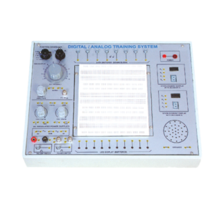
Digital / Analog Training System
Solderless Breadboard has 1680 tie points. Provided with 2 Terminal strips and 4 Distribution strips. Built in DC Regulated Power Supply. DC Supply ± 5V/ 1 Amp. 0 to ± 15V DC (Variable), 1 Amp. Built-in Function Generator. . Waveform : Sine, Square and Triangle (with selector switch),
Frequency : 1 – 100 Hz Variable
Amplitude : Variable up to 10 V, TTL 5V p-p
Data Switches (Bounceless) – 8 No.
LED Display (buffered) – 10 No.
Clock Pulsar – 2 No.
Seven Segment Display with Decoder IC 7447 – 2 No.
Speaker 2.5 Dia. with sockets – 1 No.
BNC Plug with 2 mm Sockets – 2 No.
4 mm socket connected with 2 mm sockets – 2 No.
Interconnection leads having 2 mm plugs at one end – 10 No.
Interconnection leads having 4 mm plugs at both end – 10 No.
22 SWG Hook Up Wire of 20 cm length – 100 No.
Comprehensive User’s Manual – 1 No.
Input 220 V, 50 Hz. AC with On/Off indicator.
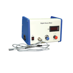
Digital Gauss Meter
Digital Gauss meter works on the principle of Hall Effect in semiconductor. When a semiconductor with current flowing in one direction is introduced perpendicular to a magnetic field a voltage is produced at right angles to the current path. The magnitude of this voltage is proportional to the intensity of the magnetic field. This voltage is called Hall Voltage. This Hall voltage is amplified and calibrated as magnetic field.
Specifications:
Range: 0-2 KG & 0-20 KG
Resolution: 1 G at 0-2 KG range
Display: 3½ digit LED
Power Supply: 220 V, ±10%, 50 Hz AC
Transducer: Hall probe-InAs
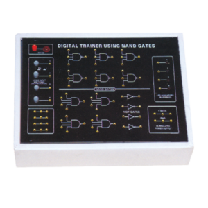
Digital Trainer Using NAND Gates
Complete with Regulated power supply of + 5V/500 mA. Provided with 4 Logic input switches (bounceless) 4 LED Indicators (Buffered)
Functional diagram of :-
1. 3 Input NAND 6 No.
2. 4 Input NAND 4 No.
3. 1 Input NOT Gates 4 No. is printed on board.
4. 12 Interconnection Leads and User’s Manual is provided.
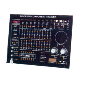
Discrete Component Trainer
Trainer consisting of Power Supply of +5 V / ±12 V (each of 250 mA), Silicon, Germanium diodes, Zeners, PNP and NPN Transistors, FET, One speaker, 12 different values of carbon film resistances of ¼ W, ½ W and 1 W. 12 assorted values of capacitors from 100 pF to 1000 ?F, Integrated Circuit (IC) Base and IC 74LS00 1 No. each. LED, LDR, Photo diode, Solar Cell Logic Switches (4 No.) and LED Indicators (4 No.) etc., 2 mm Interconnection Leads -10 No. and Comprehensive User’s Manual
Electronics Kit
Emitting Diode (LED’s)
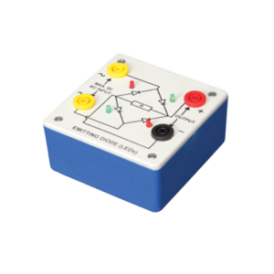
Bridge rectifier is designed with four LEDs internally arranged in bridge pattern fitted inside a plastic moulded case. Two LED’s are red and two LED’s are green. This device is used to demonstrate the functioning of a bridge rectifier, i.e., to convert alternating current (AC) into direct current (DC). Two yellow sockets are used for AC input. Two sockets, one red and one black, are used for DC output. For the easy understanding of the internal circuitry, the circuit diagram is printed on the box.
Fiber Optics Communication Set
Objective:
To construct an optical transmitter and transmission of signal through Fiber Optics Cable. To construct an Optical Receiver and study the Attenuation of Signal when transmitted from Transmitter to Receiver end. Analog and Digital link can also be studied as this unit is complete with Sine and Square Waves. Bending losses can also be studied.
Features:
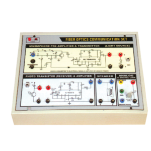
Instrument comprises of Microphone Preamplifier stages consists of MIC (Microphone), Preamplifier and Amplifier (Voice is converted to electrical signal and then amplified) and fed to LED (Transmitter) and then through fibre cable, signal is sent to Photodetector (Transistor) and again amplifier and output is sent to Speaker Unit. Power Supply of +6 VDC is used in Amplifier ckt. 2 No. Fiber Optics cables are provided (one of them is 50 cm long and the other is 100 cm long). One more fiber cable of 50mm length having connector at one end is also provided. Connectors a both end of fiber cable are provided for insertion in sockets provided on the front panel. Bending losses can also be studied in long wire.
Standard: MIC with 2 meter long lead and a Speaker 4, 4 ohm are mounted in a vertical box.
Accuracy: with 1 meter long connecting leads. 2 No. Fiber optic cable having length of 50 cm and 100 cm are provided.
Optional : Digital multimeter (3 1/2 Digit, Big size Display) This model also include Digital Multimeter and wooden frame for measurement of Numerical aperture i.e. complete in all respect including facility for measurement of numerical aperture.
Frequency Modulation And Demodulation
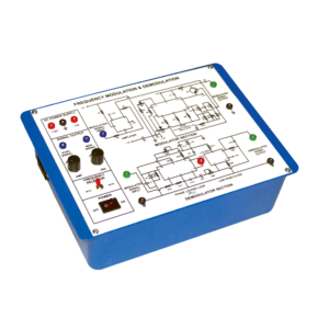
This Instrument is design to demonstrate the method to transmit signals via. Electromagnetic transmission and to study the Frequency Modulation and Demodulation. Whole instrument is placed in plastic moulded box and 2 mm banana plug leads are provided for modulation and demodulation connections.
Technical Specification:-
1. Fixed Output DC Regulated Power Supply of ±12 V.
2. Built in Modulating signal Generator of 2 KHz and 4 KHz selectable with a toggle switch with Amplitude to 3V peak to peak approximately.
3. Circuit diagrams for Modulator and Demodulator are printed on the milky white top panel
Frequency Shift Keying Modulation And Demodulation
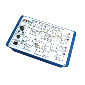
This Instrument is design to demonstrate the method to transmit signals via. Electromagnetic transmission and to study the Frequency Shift Keying Modulation and Demodulation. Whole instrument is placed in plastic moulded box and 2 mm banana plug leads are provided for modulation and demodulation connections.

