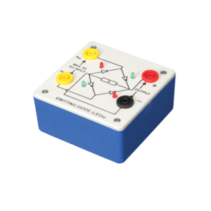
Bridge rectifier is designed with four LEDs internally arranged in bridge pattern fitted inside a plastic moulded case. Two LED’s are red and two LED’s are green. This device is used to demonstrate the functioning of a bridge rectifier, i.e., to convert alternating current (AC) into direct current (DC). Two yellow sockets are used for AC input. Two sockets, one red and one black, are used for DC output. For the easy understanding of the internal circuitry, the circuit diagram is printed on the box.
Objective:
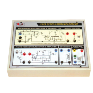
To construct an optical transmitter and transmission of signal through Fiber Optics Cable. To construct an Optical Receiver and study the Attenuation of Signal when transmitted from Transmitter to Receiver end. Analog and Digital link can also be studied as this unit is complete with Sine and Square Waves. Bending losses can also be studied.
Features:
Instrument comprises of Microphone Preamplifier stages consists of MIC (Microphone), Preamplifier and Amplifier (Voice is converted to electrical signal and then amplified) and fed to LED (Transmitter) and then through fibre cable, signal is sent to Photodetector (Transistor) and again amplifier and output is sent to Speaker Unit. Power Supply of +6 VDC is used in Amplifier ckt. 2 No. Fiber Optics cables are provided (one of them is 50 cm long and the other is 100 cm long). One more fiber cable of 50mm length having connector at one end is also provided. Connectors a both end of fiber cable are provided for insertion in sockets provided on the front panel. Bending losses can also be studied in long wire.
Standard: MIC with 2 meter long lead and a Speaker 4, 4 ohm are mounted in a vertical box.
Accuracy: with 1 meter long connecting leads. 2 No. Fiber optic cable having length of 50 cm and 100 cm are provided.
Optional : Digital multimeter (3 1/2 Digit, Big size Display) This model also include Digital Multimeter and wooden frame for measurement of Numerical aperture i.e. complete in all respect including facility for measurement of numerical aperture.
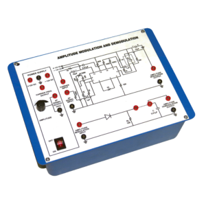
Instrument is design to demonstrate the method to transmit signals via. Electromagnetic transmission. It is still used in radio system to transmit audio signal although it has lesser in popularity compared to FM (Frequency Modulation) due to its lower signal to noise ratio.
Technical Specification :-
1. I C based DC regulated Power Supply ±12 V / 500 mA.
2. Audio frequency 1 KHz / 0-2 Vpp for modulating signal 455 KHz / 2.5 Vpp approx. for Carrier Frequency.
This Trainer Consist of :
1. Regulated power supply of ± 12 V / 250 mA.
2. Variable 0 to ±5 V / 250 mA.
3. Sine wave oscillation of 1 KHz.
4. Digital Voltmeter of 0-20 V DC, LCD display, 3 ½ Digit.
5. Functional diagram of IC 741 is printed with 2 mm sockets.
6. One extra 8 pin IC Base with 2 mm sockets.
7. Potentiometer of 10K Ohms.
8. Required Resistance and Capacitances mounted on board.
9. Interconnection Leads and Manual to perform 15 experiments on IC741 e.g. inverting, non-inverting, summing, difference, multiplier, differentiator, integrator etc.
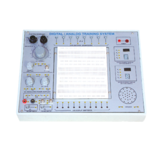
Solderless Breadboard has 1680 tie points. Provided with 2 Terminal strips and 4 Distribution strips. Built in DC Regulated Power Supply. DC Supply ± 5V/ 1 Amp. 0 to ± 15V DC (Variable), 1 Amp. Built-in Function Generator. . Waveform : Sine, Square and Triangle (with selector switch),
Frequency : 1 – 100 Hz Variable
Amplitude : Variable up to 10 V, TTL 5V p-p
Data Switches (Bounceless) – 8 No.
LED Display (buffered) – 10 No.
Clock Pulsar – 2 No.
Seven Segment Display with Decoder IC 7447 – 2 No.
Speaker 2.5 Dia. with sockets – 1 No.
BNC Plug with 2 mm Sockets – 2 No.
4 mm socket connected with 2 mm sockets – 2 No.
Interconnection leads having 2 mm plugs at one end – 10 No.
Interconnection leads having 4 mm plugs at both end – 10 No.
22 SWG Hook Up Wire of 20 cm length – 100 No.
Comprehensive User’s Manual – 1 No.
Input 220 V, 50 Hz. AC with On/Off indicator.



































Reviews
There are no reviews yet.