






























XTEMOS ELEMENT
AJAX PRODUCTS TABS
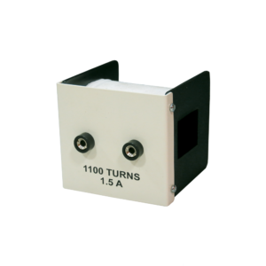
Coil, High Inductance
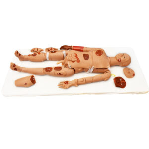
Gd Skin Color Advanced Trauma Simulator
Description
Features:
Washing, disinfection, hemostasia, enswathement etc. Open fracture, truncation trauma.Features of Advance trauma manikin:
Facial burn: I, II, IIIdegree. Laceration in forehead. The wound in jaw. Opened clavicular fracture and contusion wound on the chest. The wound in abdomen with small intension evisceration. Opened humerous fracture of right upper arm. Opened fracture of right hand (including parenchyma laceration, fracture and bone tissue exposure) Gun wound in the right palm. Opened fracture of right thighbone. Compound femur fracture of left thigh. Metal pricking wound in right thigh. Opened tibia fracture of right leg. Opened fracture of right foot with truncating trauma on small phalanx. Burns in left forearm: I, II, III degree. Truncating trauma on left thigh. Closed tibia fracture of right leg and contusion wounds in left ankle and foot.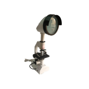
Projection Microscope
Specifications
Projection Microscope is a dual purpose instrument which is equipped with the halogen projection bulb that works efficiently on the power supply of 220AC. The device is fitted with the highly effective cooling fan inside the instrument. The device is equipped with the fine grain glass screen which is provided to take the image on the screen or wall of the instrument with the magnification range up to 400X. The instrument is supplied complete with the vinyl cover in a packing of a cardboard box. It is easy to operate instrument that offers highly accurate test results. The instrument provides high-quality and clear images. The instrument is equipped with the fine grain glass screen which is provided to take the image on the screen or wall of the instrument with the magnification range up to 400X. It is a dual purpose instrument which is equipped with the halogen projection bulb. The works efficiently on the power supply of 220AC. The device is assembled with the effective cooling fan inside the instrument.
Frequency Response Analysis of Lead Lag Network
Frequency response of Lead, Lag network using P+I+D controller is a special purpose analog simulation, create using operational amplifiers. This simulator permits a detailed analysis of the first order and second order systems on the application of proportional, integral and derivative control to the improvement of their performance. The simulator may be used at high frequency for oscilloscope observation.
FEATURES:
• Built-in Function Generator (sine & square). • Self contained power supplies and power ON/OFF switch with indication. • Full mimic diagrams in the front panel. • The simulated process. - Simple Lag Process - Simple Lead Process • The simulated PID controller - Integral controller scaled in Integration time. - Derivative controller scaled in derivative action time. - Proportional band control scaled in % proportional band (PB).XTEMOS ELEMENT
AJAX PRODUCTS TABS SIMPLE

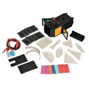
Light Box and Optical Set
Description
A Robust light box in matt black finish with a 12 V 24 W axial filament lamp with flexible leads. One end of the box takes a cylindrical convex lens in an adjustable sliding mount to enable production of convergent, parallel or divergent beams. Complete with accessories which consist of: 5 Plastic blocks, one rectangular, One semicircular, One equilateral prism 60° x 60° x 60°, One right angle prism 90° x 60° x 30° and one right angle prism 90° x 45° x 45°. 3 Cylindrical acrylic lenses: one double convex, one double concave, both having the same radius of curvature and one thick convex lens. 3 Mirrors, one plane glass, one curved parabolic and one curved semi-circular. 2 Slit plates, one with three narrow and one narrow slits, the other with four narrow and one wide slits 1 Set of eight colour filters, Red, Green, Blue, Cyan, Violet, Yellow, Orange and Magenta. 1 Set of coloured cards, Red, Green, Blue, Violet, Orange, Cyan, Yellow and Pink. Complete with one spare lamp, in box.
Tubing, Rubber
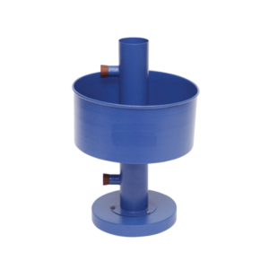
Hope’s Apparatus
XTEMOS ELEMENT
AJAX PRODUCTS TABS ALTERNATIVE
Fashion
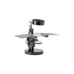
Dissecting Microscope with Bull Lens
Specifications
Heavy stable round base, Focusing done by Rack & Pinion system, with stopper to limit the downward movement of the Eye piece towards stage. A adjustable holder is provided for moving magnifying lens over full area of the stage. It is easily replacable with Bull Eye Lens 80mm in dia. A plano concave mirror in fork mount for light reflection, sturdy removable hand rests and arrangement for inserting Black & white plate. Duly packed in wooden cabinet with the following optics:| Eye piece: | 10x & 15X and Bull Eye Lens 80mm dia. | |
| Stage size: | 100mm x 100mm |


XTEMOS ELEMENT
AJAX PRODUCTS TABS ARROWS PAGINATION

SENIOR RESEARCH BIOLOGICAL MICROSCOPE
BIIC-220 Series
Micron BMC-220 is the newly introduced series o[educational Microscope which extend top quality optics and uncompromising performance for educational and routine research work.
Features :
- Mechanical tube length 160 mm.
- 45 inclined with 360 degree rotatable binocular head.
- Co-axial built in Mechanical stage 140 x 140 mm with fine vernier graduation, designed with convenient coaxial adjustment forjerk free smooth slide manipulation through 55 x 75 mm.
- Dust proof quadruple/ quintuple ball bearing revolving nose piece with positive click stops.
- Co-axial coarse & fine focusing adjustment knobs on ball bearing guide ways. Fine motion, graduated to .002 mm.
- Staple Grey, chemical resistant, back-on finish.
- Adjustable focus lock prevents damage to valuable slide and objectives.

Linear Air Track
Angular section aluminium alloy track, length 255cms, with staggered air holes, supported on two light alloy castings positioned 45 cm from each end of the track.
One support has a two- point contact and other one-point contact for lateral and horizontal adjustments for which a knurled screw is provided.
Large catapult arms with slots for elastic bands are fitted to each end of the track.
A fully fitted to one end of the track enables experiments involving acceleration under a constant force.
Identical end caps enable air to be introduced from either end of the track, bung being supplied to close the end not being used.
The vehicle buffer attachments and clamping screws are matt black to help interpretation of stroboscopic photographs.
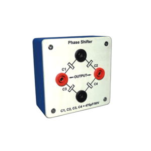
Phase Shifter
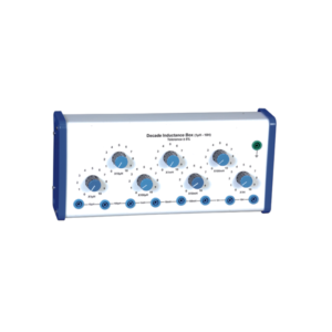
Decade Inductance Box – 7 Dial
Description
Housed in a box with seven dials and fitted with 4 mm output plugs, the unit allows a range of inductances from 1ΩH to 10ΩH. 7 Decade Inductance Box (i) 1ΩH to 10ΩH in steps of 1ΩH (ii) 10ΩH to 100ΩH in steps of 10ΩH (iii) 100ΩH to 1mH in steps of 100ΩH (iv) 1mH to 10mH in steps of 1mH (v) 10mH to 100mH in steps of 10mH (vi) 100mH to 1mH in steps of 100mH (vii) 1mH to 10mH in steps of 1mHXTEMOS ELEMENT
AJAX PRODUCTS TABS WITH ICONS
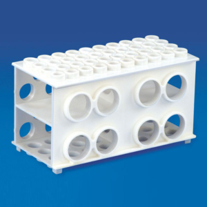
Universal Multi Rack
Avail from us high quality Universal Multi Rack at affordable price range.
Souced from reliable vendors, this rack is an excellent lab apparatus compatible with different sizes of tubes.
Four sides of this rack can be used for tubes of 30mm, 20mm, 17mm & 12mm.High grade Polypropylene is used for its manufacturing.
Material : Polypropylene
| Particulars | Pack (Pcs) | |
|---|---|---|
| Universal Multi Rack | 6 | |
| Rotatable Multi Rack | 1 |


RAY OPTICS KIT

Refrigerant Charging Unit
This charging unit is fitted with motorised vacuum pump and other safety devices like pressure gauge. With the help of this charging unit students can charge the refrigerant gases into compressor or store the gas of a refrigerator or air conditioner inside the cylinder fitted inside the charging unit that can be used later.
XTEMOS ELEMENT
AJAX PRODUCTS TABS LOAD MORE PAGINATION

SILICA CRUCIBLE WITHOUT LID
PRODUCT DESCRIPTION
- Crucible is glazed inside and outside.
- Highly resistant to alkalis and hot temperatures
- 50ml capacity
- Outside diameter 55mm, 42mm height
- No lid includedSilica crucible is glazed inside and outside. Highly resistant to alkalis and hot temperature SIZES ARE: 15ML 25ML 50ML 80ML 100ML 150ML

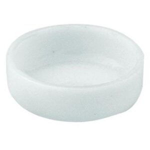
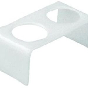
SILICA CRUCIBLE TALL FORM Without Lid, Translucent
XTEMOS ELEMENT
AJAX PRODUCTS TABS CAROUSEL
Transducer Trainer
Specification
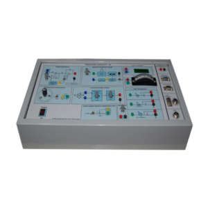
• RTD acts as a temperature sensor • Strain gauge based load cell • Linear variable resistive transducer • LDR, Photo diode, photo transistor • Precision servo potentiometer • Inductive type proximity sensor • Heat source, Filament lamp, Buzzer • 3½ digit LED display • Analog type 10V Center-Zero meter • Inverting and Non-inverting amplifier • Amplifier with Gain and offset control • Instrumentation and summing amplifier • Low pass filter • Precision Rectifier • Timer and buzzer oscillator • Electric switch
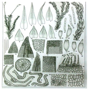
Bryophyta
| Anthoceros Thallus VS | Anthoceros Cporophyte LS |
| Marchantia Thallus VS | Marchantia Gemma Cup VS |
| Marchantia Antheridial Head VS | Marchantia Archegonial Head VS |
| Marchantia Sporophyte VS | Moss Protonema WM |
| Moss with Capsule WM | Moss Leaf TS, WM |
| Moss Archegonia WM | Moss Stem TS |
| Moss Archegonial Head WM Moss Antheridia WM | Moss Antheridia Head VS |
| Moss Capsule LS, WM | Moss Capsule TS |
| Porella Veg. WM | Porella Antheridial WM |
| Porella Archegonial WM | Riccia Thallus TS |
| Riccia Antheridial VS | Riccia Thallas WM |
| Riccia Archegonial VS | Riccia Mature Sporophyte VS |

