XTEMOS ELEMENT
AJAX PRODUCTS TABS


Pilot Static Tube Set Up
DESCRIPTION:-
A Pitot tube is used to measure the local velocity at a given point in the flow stress. A Pitot tube of standard design made of copper / SS is supplied and is fixed below Vernier scale. The Vernier scale is capable to measure the position of Pitot tube in transparent pipe section. The pipe has a flow control valve to regulate the flow. A U-tube manometer is provided to determine the velocity head. Present Set-up is self-contained water re-circulating unit, provided with a sump tank and a centrifugal pump etc. Flow control valve and by-pass valve are fitted in water line to conduct the experiment on different flow rates. Flow rate of water is measured with the help of measuring tank and stop watch.EXPERIMENTS:-
Ø To find the point velocity at the center of a tube for different flow rates of water and calibrate the Pitot tube Ø To plot velocity profile across the cross section of pipeUTILITIES: –
Ø Water Supply & Drain Ø Electricity Supply: Single Phase, 220 VAC, 0.5 kWTECHNICAL SPECIFICATION: –
Ø Pitot Tube : Material Copper/SS of compatible size fitted with Vernier Scale Ø Test Section : Material Clear Acrylic, Compatible to 1” Dia. Pipe Ø Water Circulation : FHP Pump, Crompton / Sharp make Ø Flow Measurement : Using Measuring Tank, Capacity 40 Ltrs. Ø Sump Tank : Capacity 70 Ltrs. Ø Stop Watch : Electronic Ø Control Panel : On / Off Switch, Mains Indicator etc. Ø The whole Set-up is well designed and arranged in a good quality painted Structure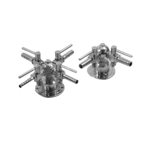
Gas Tap, Economy
Description
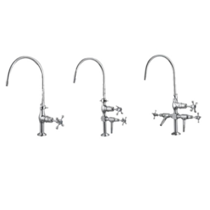
Made of brass with superior chrome plating. Output nozzle having 6mm bore. Inlet 1/2 X 14. Flange diameter 46mm with two holes to fix on bench or any other surface with screws. To be fitted directly on fitting. Designed to operate at pressure up to 2 psi (0. 14kg/cm2). Suitable for use with coal gas, natural gas and L.P.G.Particulars
Gas Tap, One Way Gas Tap, Two Way Gas Tap, Three Way Gas Tap, Four Way
Ranging Rod
XTEMOS ELEMENT
AJAX PRODUCTS TABS SIMPLE

Medical Microscope
Specification
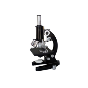
Medical Microscopes is a straight tube monocular research microscope. The body can be inclined up to 90° with separate coarse and fine adjustment. Triple revolving nose-piece, double lens condenser numerical aperture of 1.2 with iris-diaphragm and rack-n-pinion adjustment. Fixed slide stage with detachable mechanical stage, plano-concave reflecting mirror inter-changeable with removable LED microscope lamp. With 10x, 15x or 5x hymenia eyepieces (2 Nos.) 10x, 45x, 100x oil-immersion (spring loaded) achromatic objectives. Magnification : up to 1500x.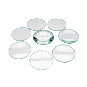
Lens, Double Convex, Spherical
Description
Clear glass, ground edges
| Focal length | Power | Add To Enquiry |
|---|---|---|
| 25 mm | 100 mm | +10D |
| 25 mm | 150 mm | +6.6D |
| 38 mm | 50 mm | +20D |
| 38 mm | 100 mm | +10D |
| 38 mm | 150 mm | +6.6D |
| 38 mm | 200 mm | +5D |
| 38 mm | 250 mm | +4D |
| 38 mm | 300 mm | +3.3D |
| 38 mm | 500 mm | +2D |
| 38 mm | 1000 mm | +1D |
| 50 mm | 50 mm | +20D |
| 50 mm | 100 mm | +10D |
| 50 mm | 150 mm | +6.6D |
| 50 mm | 200 mm | +5D |
| 50 mm | 250 mm | +4D |
| 50 mm | 300 mm | +3.3D |
| 50 mm | 500 mm | +2D |
| 50 mm | 1000 mm | +1D |
| 60 mm | 100 mm | +10D |
| 60 mm | 200 mm | +5D |
| 60 mm | 300 mm | +3.3D |
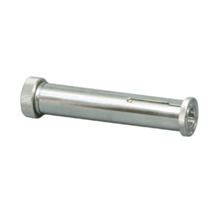
Direct Vision Spectroscope
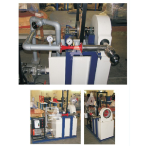
Pelton Wheel Turbine Test Setup
DESCRIPTION:
Pelton Wheel Turbine is only impulse water turbine now in common use named in honor of Sir L.A. Pelton (1829-1908) of California, USA. It is a tangential flow impulse turbine. The water strikes the buckets along the tangent of the runner. The energy available at the Inlet of the Turbine is only kinetic energy. The Pressure at the Inlet and Outlet of the atmospheric. This turbine is used for high heads. The Present Set-up consists of a runner. The buckets are mounted on the runner. The water is fed to the turbine, through SS nozzle with a SS spear, by means of Centrifugal Pump, tangentially to the runner. Row of water into turbine is regulated by adjusting the spear position by the help of a given hand wheel the runner is directly mounted on one end of a central SS shaft and other end is connected to a brake arrangement. The circular window of the turbine casing is providing with a transparent acrylic sheet for observation of flow on to the buckets. This runner assembly is supported by rigid MS structure. Load is applied to the turbine with the help of this brake dynamometer so that the efficiency of the turbine can be calculated. Pressure Gauge is fitted at the Inlet of the turbine to measure the total supply head to the turbine.EXPERIMENT:
1.To study the operation of a Pelton Wheel Turbine 2.To determine the Output Power of Pelton Wheel Turbine 3.To determine the Turbine EfficiencyUTILITIES REQUIRED:
● Water Supply and Drain.● Electricity 15 kW, 440V AC, Three Phase
TECHNICAL SPECIFICATIONS:
| MODEL | HM 111 (1.33 HP) | HM 111 (2 HP) | HM 111 (5 HP) |
| Output Power | 1.33 HP / 1 Kw | 2 HP / 1.5 Kw | 5 HP / 3.75 Kw |
| Discharge | 300 LPM (Approx.) | 400 LPM (Approx.) | 630 LPM (Approx.) |
| Supply Head | 25 m | 40 m | 45 m |
| Rope Brake Dynamometer | Dia 200 mm | Dia 200 mm | Dia 300 mm |
| Sump Tank | Capacity 150 Liters. | Capacity 200 Liters. | Capacity 300 Liters. |
| Water Circulation Centrifugal Pump | Capacity 5 HP, Three Phase | Capacity 7.5 HP, Three Phase | Capacity 15 HP, Three Phase |
| Speed | 1000 RPM (approx.) | ||
| Impeller | Material Brass, Bucket type | ||
| Nozzle | Material Stainless Steel/Mild Steel | ||
| Spear | Material Stainless Steel/Mild Steel | ||
| Discharge Measurement | Pitot Tube with Manometer | ||
| Control Panel | Star/Delta Starter, Mains Indicator, MCB for overload protection | ||
| The whole set-up is well designed and arranged in a good quality painted structure. | |||
XTEMOS ELEMENT
AJAX PRODUCTS TABS ALTERNATIVE
Fashion
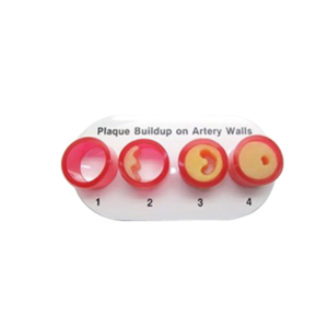
Plaque Building Anatomical Models

Basic Electro Pneumatic Trainer Kit
Features
• This trainer kit helps to design the circuits with logic sequence. • FRL unit receives air from compressor then filters, regulates & lubricates the air. • 5/2 direction control valve provided to control the double acting cylinder. • 3/2 direction control valve provided to control the single acting cylinder. • One way flow control valves provided to control the air flow. • Magnetic read switches are provided to indicate the position of the cylinder. • Control module controls the direction control valves using Switches, Relays and Timer.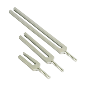
Tuning Forks Set, Even Frequency

Millikan’s Oil Drop Apparatus
XTEMOS ELEMENT
AJAX PRODUCTS TABS ARROWS PAGINATION
Rain Gauge
Description
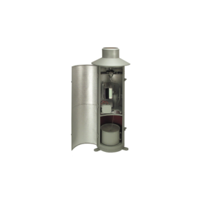
Rain gauge is designed to measure the precipitation. This small Version consisting of upper and lower housing part, measuring cylinder; Housing made of stainless steel, orifice rim made of brass. Type 7019.0000 can be supplied with a receiving area of 100 cm2. (This type is not conforming to meteorological standards). • Receiving area : 100 cm². • Rain measure (graduated glass) : 250 cm³. • Measuring range : 0 t0 25 mm precipitation (relative to a receiving area of 100 cm²). • Graduation : 1/1 mm precipitation. • Dimensions : dia 115 mm; height 300 mm. • Weight : approx. 0.8 kg.
Dental Care Model (28 Teeth), PVC

Tuning Forks welch type
Description :-
Consists of aluminum tuning forks, mallet in a wooden box.
Tuning forks are stamped with frequency and note.
Set of 8 (C-256, D-288, E-320, F-341.3, G-384, A-426.6, B-480, C-512)
Set of 13 (G-100, C-128, C-256, D-288, E-320, F-341.3, G-384, A-426.6, B-480, C-512, C-1024, C-2048 and C-4096)
Set of 8 (C-256, D-288, E-320, F-341.3, G-384, A-426.6, B-480, C-512)
Set of 13 (G-100, C-128, C-256, D-288, E-320, F-341.3, G-384, A-426.6, B-480, C-512, C-1024, C-2048 and C-4096)
XTEMOS ELEMENT
AJAX PRODUCTS TABS WITH ICONS
Force Table
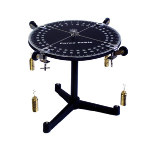
To verify the law of composition and resolution of forces consisting of a aluminium table 40cm in dia.
its raised rim has a engine divided scale, graduated in 360° mounted on heavy vertical support rod & tripod base provided with leveling screws.
Body under study in a ring in center of the table fastened by cords passing over four pulleys attached with the table.
Complete with four pulleys, four weights hangers twelve weights (2x10gm, 2x20gm, 4x50gm, 4x100 gm.)
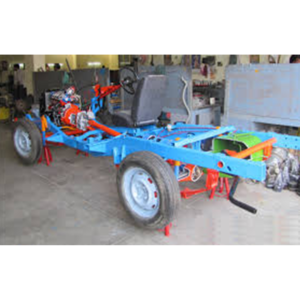
Car Chassis All Wheel Drive Actual Cut Section
Car Chassis Rear Wheel Drive Actual Cut Section – Motorised
4 Stroke 4 Cylinder Petrol Engine With Clutch, Gear Box, Propeller Shaft, & Rear Axle Assembly With Differential Gear
The chassis of the four stroke four cylinder engine cut section model. The cut section model is constructed such that all the following systems can be demonstrated in working conditions.
ENGINE:
Maximum parts and accessories of an engine like cylinders, cylinder head, inlet and Exhaust manifolds, FIP, injectors, self-starter, alternator, water pump, radiator, etc., are sectioned to show the internal constructional details. The complete sectioned model is coupled with FHP 220/230V A.C single phase motor through a Reduction drive unit.TRANSMISSION SYSTEM:
This system consists of a Clutch and four speed gearbox assembly, the casing of which is suitably cut to demonstrate its operation. The gearbox is coupled to Differential gear box with propeller shaft and the different coupling used for this transmission can be demonstrated. The Differential gear box is also cut so as to clearly to demonstrate its complete operating principle. The gear shifting including the forward and reverse gear operation can be clearly shown. The speed variation and the rotation of the Differential gear box can be seen while gear shifting. By running the motor connected to the engine assembly the entire system with gear box, rear axle etc. can be demonstrated in running. FUEL SYSTEM: The Fuel tank is cut to expose the mounting of the level sensor and the position of Fuel section. The system is complete with mechanical Fuel pump. EXHAUST SYSTEM: It consists of Exhaust Manifold and silencer in cut section to explain internal construction. LUBRICATION SYSTEM: It consists of the engine Lubrication system along with the Lubrication oil pump is suitably sectioned. SUSPENSION SYSTEM: This will explain both the Hydraulic Suspension systems at the front and the leaf spring Suspension at the Rear. One of the hydraulic arrangements of Suspension mechanism is highlighted (with shock absorbers) and explained cut sectionally.BRAKING SYSTEM:
The Hydraulic or Air circuit Brakes. The movement of the Brake Shoes on operating the brake pedals can be seen in the area where the Brake drum is cut. The front and rear brakes will be operational. STEERING MECHANISM: The can be seen and included in the Steering wheel. Steering gear box and coupling of the same to the wheels will be shown by rotating the steering wheel, the operation of the steering system can be demonstrated. The entire system will be mounted on the chassis, and suitable mounting option with caster wheels will be provided for easy movability.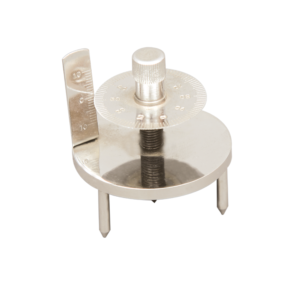
Spherometer
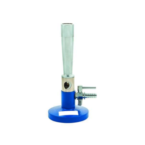
Meker Burner, with Stopcock
XTEMOS ELEMENT
AJAX PRODUCTS TABS LOAD MORE PAGINATION
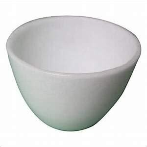
SILICA CRUCIBLE WITHOUT LID
PRODUCT DESCRIPTION
- Crucible is glazed inside and outside.
- Highly resistant to alkalis and hot temperatures
- 50ml capacity
- Outside diameter 55mm, 42mm height
- No lid includedSilica crucible is glazed inside and outside. Highly resistant to alkalis and hot temperature SIZES ARE: 15ML 25ML 50ML 80ML 100ML 150ML
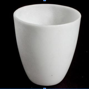
SILICA CRUCIBLE TALL FORM Without Lid, Translucent
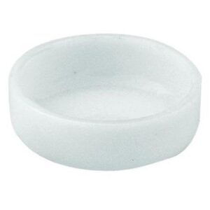
XTEMOS ELEMENT
AJAX PRODUCTS TABS CAROUSEL
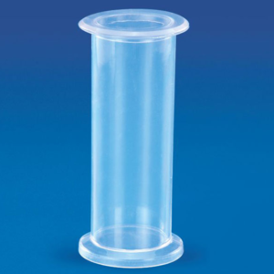
Specimen Jar
We have come up with a quality range of Specimen Jars.
These transparent Specimen Jars are used for preserving different specimens in the lab and are provided with a cap that fits in tight.
These jars provided excellent protection to the species preserved in it.
Material : Polystyrene
| Particulars | Pack (Pcs) | |
|---|---|---|
| Specimen Jar (Gas Jar) | 12 |
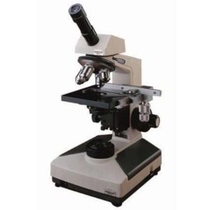
PATHOLOGY INCLINED MONOCULAR MICROSCOPE
PRODUCT DESCRIPTION:
OBSERVATION HEAD: MONOCULAR Inclined at 45° and Rota table 360º with perfectly centered Quadruple BAL Bearing revolving nose piece. OBJECTIVE- 4/5x, 10x, 40/ 45x, 100x (oil). EYE PIECES- 10x WF (one), Huygenian 5x or 15x (Any one)MECHANICAL STAGE: Double plate 130x140 mm Low drive mechanical stage for X & Y movement with Sub stage bright field condenser N.A. 1.25 & iris diaphragm with built in swing out filter holder and up-down movement through rack & pinion. FOCUSING SYSTEM: Separate Coarse & highly sensitive fine movement mechanical graduated to 0.02mm. With locking device. EXTRA LARGE BASE: To support the robust arm, has built in with LED cooled bright Illumination or 6V 20 W HALOGEN LAMP with soft start continuously variable intensity controlled regulator & quick change bulb provision. PACKING: Microscope supplied one Plano concave mirror for use in day light, duster, cover & instruction manual.

89C51 Development Board
Specification:
• High Performance MCU:P89V51RD2 8 bit with 64K program flash, 1xUART, 4x 8bit I/O, 4level priority,7 interrupt sources, upto 40 MHz operation • All the IO lines are terminated through 4nos Pin FRC Connectors • One SPDT Switch provided for PROG/EXEC mode selection and one SPDT switch for Power ON/OFF Control. • RS232 interface with two status LEDs for Programming and UART interface • One 8 – way DIP switch for Digital Logical Input • On board 8 Leds for Digital Logial Output • 4x4 Matrix Keypad, On board 16x2 LCD • On board RTC interface with four function keys • Two 12V relay with driver Circuit for DC Motor 0.5 Kg Stepper Motor with relevant driver circuit • On board DAC terminated via 2-pin Phoenix Connector • On board 8 channel ADC with Temperature sensor