XTEMOS ELEMENT
AJAX PRODUCTS TABS

Advanced Surgical Suture Arm
Description
Interchangeable arterial and venous inserts within the fore arm allow creation of arteriovenous (AV) fistulas and placement of AV grafts, while a simulated healed fistula insert provides a platform on which hemodialysis exercises can be performed. An additional multi-layer insert in the bicep area can be used for incision and suture training exercises.Advanced Arterial Patient Training Arm Features:
Subcutaneous injection sites on the volar forearm and lateral upper arm Intra Muscular injection site on the upper arm Arterial system including the radial and brachial arteries Suture and incision sites on both the upper arm and forearm Hem dialysis site on the forearm Arterial and Venous insert for IV and blood draw exercises, AV anastomosis, and placement of AV grafts. This multi-layer surgical insert includes the skin, subcutaneous tissue, muscle, radial artery, and radial vein AV fistula insert that simulates a healed fistula for hem dialysis exercises. Multi-layer bicep insert that includes the skin, subcutaneous tissue, and muscle and allows incision and suturing exercises Durable skin that can be pierced in excess of 200 times with a 20 or 22 gauge needle Realistic tactile feedback for both surgical and arterial & venous stick exercises Adjustable heart rate and pulse strength simulating a heart rate from 10 BPM to 150BPM Cephalic (antecubital), Basilic, Radial, and Ulnar veins as well as the radial and brachial arteries for infusion and blood draw. Rotating arm allowing dorsal and volar access along the length of the arm. Varying vessel palpability to simulate collapsed or bulging vessels and ease of assembly. Latex-Free New proprietary materials replicate of skin, subcutaneous, and muscle layers at all surgical sites. Upgraded inserts, skins, and vessels for improved tactile feedback Micro pump embedded within the shoulder generates variable heart rates and pulse strength. Easy to replace plug-and-play inserts to allow quick change-out between procedures. Latex-free vessels with improved access for hassle-free replacement.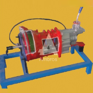
Synchromesh Gear Box 4 Forward 1reverse With Clutch Plate
Synchromesh Gear Box – 4 Forward & 1Reverse Actual Cut Section With Single Plate Clutch
The working of gear box is shown with the help of actual parts assembled on square iron pipe frame. All the necessary parts of gear box are shown in actual working form. This model helps the student to understand the working of the gear box very easily. It is specially made dissectible for demonstration purposes.
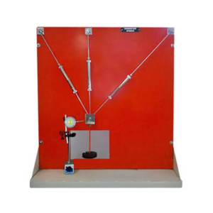
Polarising Filter Stress Determination
Description
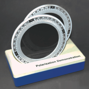
Demonstrate stress patterns in solids with this new and valuable equipment. Two polarising filters, mounted on a graduated frame are placed on a plastic base. Clear acrylic pieces of different shapes are introduced between the filters; when pressure is applied to the solids the resulting stress patterns are observed. An important method of demonstrating polarisation and stress. Includes instructions.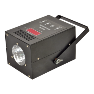
Digital Stroboscope
Description :-
Stroboscopic flashes are triggered by either the internal oscillator or by external pulses which may be connected to the two 4mm sockets mounted on the rear panel of the instrument. Example of the many applications of this unit are to be found in motion analysis multi exposures photography, examination of moving parts and measurement of rotational speed.
Specifications:-
Input Volts : 220V AC, 50 Hz
Flash Rate: 0- 9999 Flashes per minute.
Resolution : 1
Display: 7 Segment LED (4 nos.)
XTEMOS ELEMENT
AJAX PRODUCTS TABS SIMPLE
Car Chassis Front Wheel Drive Actual Cut Section
Car Chassis Rear Wheel Drive Actual Cut Section – Motorised
4 Stroke 4 Cylinder Petrol Engine With Clutch, Gear Box, Propeller Shaft, & Rear Axle Assembly With Differential Gear
The chassis of the four stroke four cylinder engine cut section model. The cut section model is constructed such that all the following systems can be demonstrated in working conditions.
ENGINE:
Maximum parts and accessories of an engine like cylinders, cylinder head, inlet and Exhaust manifolds, FIP, injectors, self-starter, alternator, water pump, radiator, etc., are sectioned to show the internal constructional details. The complete sectioned model is coupled with FHP 220/230V A.C single phase motor through a Reduction drive unit.TRANSMISSION SYSTEM:
This system consists of a Clutch and four speed gearbox assembly, the casing of which is suitably cut to demonstrate its operation. The gearbox is coupled to Differential gear box with propeller shaft and the different coupling used for this transmission can be demonstrated. The Differential gear box is also cut so as to clearly to demonstrate its complete operating principle. The gear shifting including the forward and reverse gear operation can be clearly shown. The speed variation and the rotation of the Differential gear box can be seen while gear shifting. By running the motor connected to the engine assembly the entire system with gear box, rear axle etc. can be demonstrated in running. FUEL SYSTEM: The Fuel tank is cut to expose the mounting of the level sensor and the position of Fuel section. The system is complete with mechanical Fuel pump. EXHAUST SYSTEM: It consists of Exhaust Manifold and silencer in cut section to explain internal construction. LUBRICATION SYSTEM: It consists of the engine Lubrication system along with the Lubrication oil pump is suitably sectioned. SUSPENSION SYSTEM: This will explain both the Hydraulic Suspension systems at the front and the leaf spring Suspension at the Rear. One of the hydraulic arrangements of Suspension mechanism is highlighted (with shock absorbers) and explained cut sectionally.BRAKING SYSTEM:
The Hydraulic or Air circuit Brakes. The movement of the Brake Shoes on operating the brake pedals can be seen in the area where the Brake drum is cut. The front and rear brakes will be operational. STEERING MECHANISM: The can be seen and included in the Steering wheel. Steering gear box and coupling of the same to the wheels will be shown by rotating the steering wheel, the operation of the steering system can be demonstrated. The entire system will be mounted on the chassis, and suitable mounting option with caster wheels will be provided for easy movability.

Power Supply, 2 V
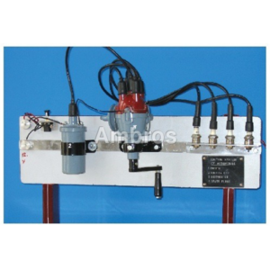
Coil Ignition System Of An Automobile
XTEMOS ELEMENT
AJAX PRODUCTS TABS ALTERNATIVE
Fashion
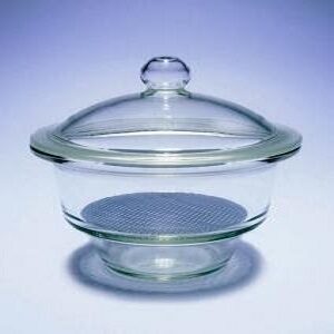
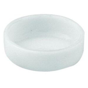
DESICATOR WITH COVER
Product description:
Desiccator, Non-Vacuum, with Base, Lid and Perforated Porcelain Plate, Soda Lime Glass
Desiccators are sealable enclosures containing desiccants used for preserving moisture-sensitive items such as cobalt chloride paper for another use. A common use for desiccators is to protect chemicals which are hygroscopic or which react with water from humidity.
Size:
100mm
125mm
250mm
500mm
1000mm

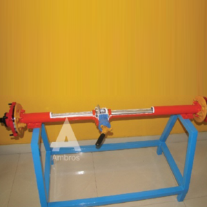
Plane Table
Description
The Plane Table Surveying Instruments include standard accessories like Trough Compass, Spirit level, Canvas cover, Plumbing Fork etc., and is also with a fitted tripod. Uses of Plane Table in Engineering Surveys: • Maps preparation • Recording topography Accessories included in Plane Table Surveying Instruments: • Plane Table Board 750 x 600 mm, thickness 22mm & 16mm • Carrying Bag for Board • Teak wood Polished Stand • Stand Rigid Brass Head & Plate, • Magnet Trough compass brass • Spirit Level brass • Sight van 24" • Plumbing Fork • Plumb Bob
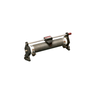
Lagged Pipe Apparatus
Lagged Pipe Apparatus:
The apparatus consists of three concentric pipes mounted on suitable stand. The space between innermost and the middle pipe is fifed with a lagging material and the space between the middle and the outer most is filled with and other lagging material. The lagged pipe is heated with a cartridge heater inserted at the axle length of the pipe. Voltmeter and ammeter on the panel can measure the input to the heater. The intermediate temperatures can be measured by the thermocouples attached at the surfaces of the pipe. Thus the resultant conductivity of the materials can be found out.
SPECIFICATIONS:
1.Pipes : a)Gl pipe (innermost) – 6 cm. (Outer Diameter). b) Gl Pipe (Middle) – 8.5 cm. (Mean Diameter) c)G! Pipe (Outermost) – 10.7 cm. (inner Diameter) d)Length of pipes 1 Meter. 2.Heater : Nichrome wire cartridge heater placed centrally, of suitable capacity. 3.Control Panel : a)Single Phase Dimmerstat – 1 No. b)Voltmeter (0 – 250V) – 1 No. c)Ammeter (0- 2A) – 1 No. 4.Temperature Indicator : Multichannel Digital Temperature Indicator ranging (0 – 300 C) using Cr/AI ThermocouplesServices Required:
1. A.C. Single Phase 230 V electric supply 2. Floor Area-1.5 Meter X 1 Meter X 0.5 Meter High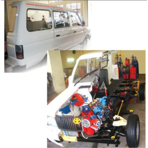
Car Chassis Rear Wheel Drive Actual Cut Section Motorised
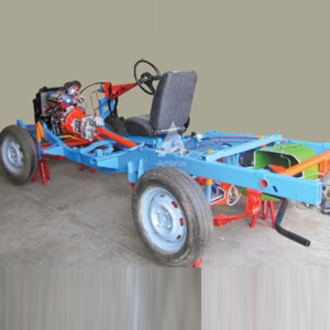
Car Chassis Rear Wheel Drive Actual Cut Section – Motorised
4 Stroke 4 Cylinder Petrol Engine With Clutch, Gear Box, Propeller Shaft, & Rear Axle Assembly With Differential Gear
The chassis of the four stroke four cylinder engine cut section model. The cut section model is constructed such that all the following systems can be demonstrated in working conditions.
ENGINE:
Maximum parts and accessories of an engine like cylinders, cylinder head, inlet and Exhaust manifolds, FIP, injectors, self-starter, alternator, water pump, radiator, etc., are sectioned to show the internal constructional details. The complete sectioned model is coupled with FHP 220/230V A.C single phase motor through a Reduction drive unit.TRANSMISSION SYSTEM:
This system consists of a Clutch and four speed gearbox assembly, the casing of which is suitably cut to demonstrate its operation. The gearbox is coupled to Differential gear box with propeller shaft and the different coupling used for this transmission can be demonstrated. The Differential gear box is also cut so as to clearly to demonstrate its complete operating principle. The gear shifting including the forward and reverse gear operation can be clearly shown. The speed variation and the rotation of the Differential gear box can be seen while gear shifting. By running the motor connected to the engine assembly the entire system with gear box, rear axle etc. can be demonstrated in running. FUEL SYSTEM: The Fuel tank is cut to expose the mounting of the level sensor and the position of Fuel section. The system is complete with mechanical Fuel pump. EXHAUST SYSTEM: It consists of Exhaust Manifold and silencer in cut section to explain internal construction. LUBRICATION SYSTEM: It consists of the engine Lubrication system along with the Lubrication oil pump is suitably sectioned. SUSPENSION SYSTEM: This will explain both the Hydraulic Suspension systems at the front and the leaf spring Suspension at the Rear. One of the hydraulic arrangements of Suspension mechanism is highlighted (with shock absorbers) and explained cut sectionally.BRAKING SYSTEM:
The Hydraulic or Air circuit Brakes. The movement of the Brake Shoes on operating the brake pedals can be seen in the area where the Brake drum is cut. The front and rear brakes will be operational. STEERING MECHANISM: The can be seen and included in the Steering wheel. Steering gear box and coupling of the same to the wheels will be shown by rotating the steering wheel, the operation of the steering system can be demonstrated. The entire system will be mounted on the chassis, and suitable mounting option with caster wheels will be provided for easy movability.XTEMOS ELEMENT
AJAX PRODUCTS TABS ARROWS PAGINATION
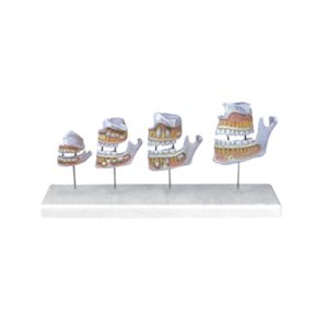
Model of Dentition development

Rods For Thermal Conductivity Experiments, Copper, Pk of 8 Rods
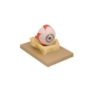
Eye Model On Bony Base

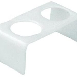
Wooden Pipette Stand, Holds 24 pipettes Vertically
XTEMOS ELEMENT
AJAX PRODUCTS TABS WITH ICONS

Specific Gravity Specimen Cylinders with Hooks

Coil Condensers , Graham, Jacket Distillate Type
Chordata Protochordata
Educational Equipments Manufacturer, Exporters & Suppliers - School Educational Equipments Manufacturers & Exporters of Educational Equipments for Lab.
Science Lab Products, Teaching Aids, Classroom Instruments, Educational Laboratory
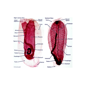
Amphioxus Entire WM
Amphioxus Pharynx Region TS
Amphioxus Gonads Region TS
Amphioxus Intestine Region TS
Amphioxus Oral-Hood TS
Amphioxus Tail Region TS
Balanoglossus Ant. Region LS
Balanoglossus Proboscis Region TS
Balanoglossus Collar Region TS
Balanoglossus Brachial Region TS
Balanoglosus Trunk Region TS
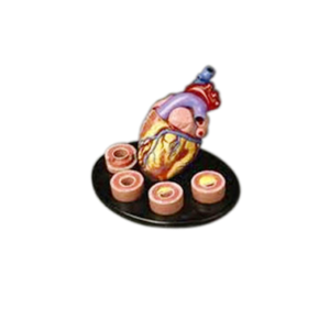
Heart With Arteries Models
XTEMOS ELEMENT
AJAX PRODUCTS TABS LOAD MORE PAGINATION
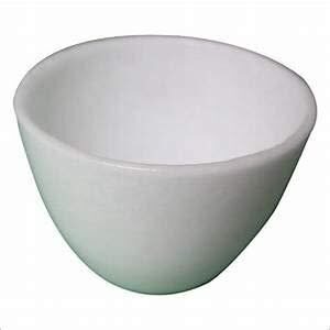
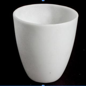
SILICA CRUCIBLE WITHOUT LID
PRODUCT DESCRIPTION
- Crucible is glazed inside and outside.
- Highly resistant to alkalis and hot temperatures
- 50ml capacity
- Outside diameter 55mm, 42mm height
- No lid includedSilica crucible is glazed inside and outside. Highly resistant to alkalis and hot temperature SIZES ARE: 15ML 25ML 50ML 80ML 100ML 150ML
SILICA CRUCIBLE TALL FORM Without Lid, Translucent
XTEMOS ELEMENT
AJAX PRODUCTS TABS CAROUSEL
Redundant Joint Apparatus
Apparatus consists of three suspension members (spring balances) of different stiffness, which are jointed at a point to form the redundant joint. The upper end of the suspension members being tied in a position to a vertical wooden board. Arrangement is provided to apply a vertical load at the joint and to measure its horizontal and vertical displacement on a paper and also elongations and forces in the suspension members by the help of dial gauges. Dial gauges with magnetic base are provided with the apparatus.
EXPERIMENT:
Comparison of experimental and theoretical results of forces in the members and the component displacement of the loaded joint D of a three bar suspension system for vertical loads.REQUIRED ACCESSORIES:
• Redundant Joint Apparatus • Dial Gauge : 1 No. • Magnetic Base : 1 No. • Hangers : 1 Nos. • Weight of 500gm : As Per requirement.
Rheostat, Single Tube
Description
A layer of oxidized resistance wire is wound on a porcelain tube which is supported by end supports. A sliding contact and three 4 mm socket terminals are provided for use as a rheostat or as a potentiometer. Other ranges also available on request.| Ohms | Ampere | Tube length | |
|---|---|---|---|
| 23 | 2.3 | 150mm | |
| 10 | 3.3 | 150mm | |
| 22 | 2.8 | 200mm | |
| 24 | 3.3 | 250mm | |
| 28 | 4.2 | 400mm |

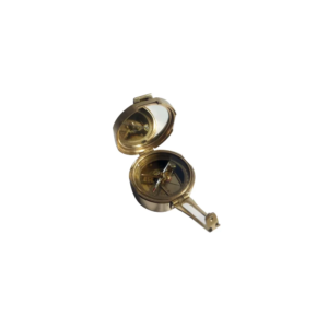
Brunton Compass
Description
We offer Brunton Compass (Geological Compass) which is available in a leather or wooden case. This compass differs from modern compasses, as it utilizes magnetic induction damping rather than fluid to dampen needle oscillation. It is widely used by geologists and surveyors to make accurate degree and angle.
Amphibia Histology
Educational Equipments Manufacturer, Exporters & Suppliers - School Educational Equipments Manufacturers & Exporters of Educational Equipments for Lab.
Science Lab Products, Teaching Aids, Classroom Instruments, Educational Laboratory
| Skin VS | Tongue TS |
| Desophagus TS | Cardiac Stomach TS |
| Pyloric Stomach TS | Duodenum TS |
| Intestine TS | Rectum TS |
| Spleen TS | Liver TS |
| Pancreas TS | Lung TS |
| Lung LS | Kidney TS |
| Kidney LS | Fat Bodies TS Ovary Immature TS |
| Ovary Mature TS | Testis TS |
| Heart LS | Heart TS through auricle |
| Heart TS through Ventricle | Blood Smear |
| Vein TS | Artery TS |
| Gall Bladder TS | Eye VS |
| Cartilage VS | Bone TS |
| Spinal Cord TS | Brain LS |
| Brain through different Regions |
Rear Axial Assembly With Differential Gear Semi
Rear Axial Assembly With Differential Gear Semi Floating Type – Actual Cut Section
The working of differential gear is shown with the help of actual parts assembled on square iron pipe frame. All the necessary parts of differential gear are shown in actual working form. This model helps the student to understand the working of the differential gear very easily. It is specially made dissectible for demonstration purposes.