XTEMOS ELEMENT
AJAX PRODUCTS TABS
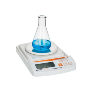
Electronic Balance
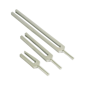
Tuning Fork, Superior
Study Of Flow Measurement Devices
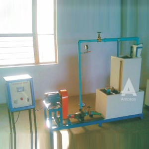
Measurement of liquid flow is required at various places and for various purposes. Different types of flow measuring devices are used depending upon the system conditions, accuracy required, skill of operator and economy desired. The unit demonstrates some of the flow measurement devices.
SPECIFICATIONS:
[1] Intergratiry Type Turbine flow meter. [2] Glass Tube Rotameter. [3] Orificemeter differential manometer. [4] Venturimeter [5] Measuring Tank [6] Stop Watch (Digital) [7] 112 HP Monoblock Pump. [8] A differential manometer. [9] Sump tank of suitable capacity. A technical manual accompanies the unit.SERVICES REQUIRED:
[1] Flow surface 2 mtrs. X 1 mtr. X 1.5 mtrs. height. [2] 230 Volts, 5 Amp. Stabilized AC.Power SupplyXTEMOS ELEMENT
AJAX PRODUCTS TABS SIMPLE
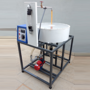
Venturimeter Orificemeter Calibration Set Up
DESCRIPTION:-
The apparatus consists of two pipelines emerging out from a common manifold. One pipeline contain a Venturimeter, second contains an Orifice. The pressure tapings from the Venturimeter and Orificemeter are taken to differential manometer to measure pressure difference. The Venturimeter and Orificemeter are connected in parallel and anyone of them can be put in operation by operating valves provided at the downstream. These valves can also regulate the flow. Present Set-up is self contained water re-circulating unit, provided with a sump tank and a centrifugal pump. Flow control valve and by-pass valve are fitted in water line to conduct the experiment on different floe rate. Flow rate of water is measured with the help of measured with the help of measuring tank and stop watch.EXPERIMENTS:-
Ø To determine the Co-efficient of discharged through Venturimeter and Orificemeter Ø To measure discharge through Venturimeter and Orificemeter as flow meters.UTILITIES: –
Ø Water Supply & Drain Ø Electricity Supply: Single Phase, 220 VAC, 0.5 kWTECHNICAL SPECIFICATIONS: –
Ø Venturimeter : Material Clear Acrylic, Compatible to 1” Dia pipe Ø Orificemeter : Material Clear Acrylic, Compatible to 1” Dia. Pipe Ø Water Circulation : FHP Pump, Crompton / Sharp make Ø Flow Measurement : Using Measuring Tank, Capacity 25 Ltrs. Ø Sump Tank : Capacity 50 Ltrs. Ø Stop Watch : Electronic Ø Control Panel : On / Off Switch, Mains Indicator etc. Ø Tanks will be made of Stainless Steel Ø The whole Set-up is well designed and arranged in a good quality painted StructureRinging Table
Emissivity Measurement Apparatus
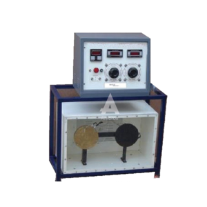
The apparatus consists of a test plate and a comparator. A black plate is used as a comparator for test plate. When all the physical, dimensions and the temperatures are equal, heat losses from both plates will also be the same, except radiation losses. Hence the input difference will be due to difference in emissive. Both the plates are kept in a panel enclose with perplex front and are given inputs through separate dimmerstats so that temperatures of both can be kept equal. Thus emissivity can determine over a wide range of temperatures.
SPECIFICATIONS:
1.Test plate and Black plates — 160mm. Dia. Aluminum plates, mounted in Panel with mica heater inside. 2.Instrumental panel consisting of- a)Voltmeter and ammeter for input measurement to both heaters through a selector switch. b)Separate dimmers for both the plates. c)Multichannel digital temperature indicator. A technical manual accompanies the unit.SERVICES REQUIRED:
1.Space area of 1.5m x 1 m. at working height. 2.230v, 15A, AC supply with earthing connectionRefrigeration And Air Conditioning Components
Actual Cut Section – Display Board (Set Of 30)
This actual cut section model is a set of thirty components used in refrigeration & air conditioning. With the help of this model students can understand the working parts of the components used in refrigeration & air conditioning. This model will be made out of original parts. The model will be suitably sectioned to demonstrate the internal construction details showing the minute information, and working of the same, the model will be suitably painted and mounted on a metal or wooden base & supplied with key card & very interesting literature regarding working of the same.
XTEMOS ELEMENT
AJAX PRODUCTS TABS ALTERNATIVE
Fashion
Orfice Mouthpieces Apparatus
DESCRIPTION:
An orifice is an opening made in the side or bottom of tank, having a closed perimeter, through which the fluid may be discharged. A mouthpiece is short tube fitted to a same size circular opening provided in a tank so that fluid may be discharged through it. Orifice and mouthpiece are used to measure the rate of flow of liquid. The apparatus is designed to measure the co-efficient of discharge of orifice & mouthpiece. The apparatus consists of a supply tank, at the side of which a universal fixture for mounting orifice or mouthpiece is attached. A centrifugal pump supplied the water to supply tank. Head over the orifice/mouthpiece is controlled by a by pass valve provided at pump discharge. A measuring tank is provided to measure the discharge. A gauge for measuring X and Y co-ordinates of jet from the orifice is provided, which is used to calculate Cv of orifice.SPECIFICATIONS:
[1] Supply Tank – 0.4 X 0.3 X 0.5m height [2] Orifice – 8mm and 10 mm. [3] Mouthpiece (a) LID = 4 (b) L/D = 1 (c) Bordas mouthpiece. (d) Convergent mouthpiece. [4] X-Y gauge for orifice jet co-ordinates. [5] Measuring tank of suitable capacity OR a calibrated water flow meter. [6] Sump tank of suitable capacity. [7] 0.5 HP pump with valve. A technical manual accompanies the unit.SERVICES REQUIRED:
[1] Flow surface 2 mtrs. X 1 mtr. X 1.5 mtrs. height. [2] 230 Volts, 5 Amp. Stabilized AC. Power Supply.Staining Box
XTEMOS ELEMENT
AJAX PRODUCTS TABS ARROWS PAGINATION
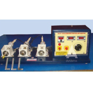
Heat Pipe Apparatus
Heat Pipe Apparatus:
Heat pipe is an interesting device, which is used to transfer heat from one location to another.
The apparatus consists of three pipes, viz. A heat pipe, copper pipe and stainless steel pipe. Ail the pipes have same physical dimensions. Copper and stainless steel pipes serve the purpose of comparison of heat pipe performance. All pipes are mounted vertically with a band heater at lower end and water filled heat sink at upper end. Nearly isothermal operation of heat pipe is clearly visualized from longitudinal temperature distribution of the pipe.
SPECIFICATIONS:
1.Heat pipe – Stainless Steel pipe, 25 mm O.D., 450 mm. Long. Sealed at both ends, evacuated and filled partially with distilled water – one No. 2.Copper and stainless steel pipe of same size as that of heat pipe – one each. 3.Equal capacity heater at bottom end of each pipe. 4.Water filled heat sinks at upper end of each pipe.Measurements and controls
a) Dimmerstat to control heat input to all the heaters – 4 amp. Capacity One No. b) A voltmeter and an ammeter to measure input to heaters One each. c) Multichannel digital temperature indictor to measure temperatures along the length of pipes.Four thermocouples are provided on each pipe. v Thermometers to note down water temperatures in heat sinks – 3 Nos.Services Required:
230 VA.C. Single Phase supply. Floor Area = 1 m X 0.5m X 0.5 m height.Material Kit Solids
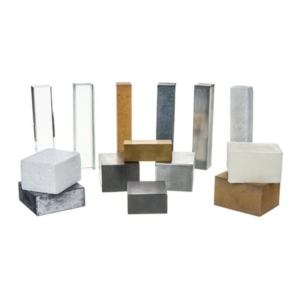
Economy Kit of 14 materials blocks.
This economy kit consist fourteen materials in the form of rectangular blocks, intended to familiarize the student with the appearance, 'feel', texture, hardness and density of a range of common substances.
Blocks, 50 x 40 x 30 mm. Wood, paraffin wax, aluminium, Iron, foamed polystyrene.
Blocks, 20 x 20 x 100 mm. Perspex, glass, slate, aluminium, softwood, Marble.
Blocks other sizes: Lead 50 x 50 x 20 mm
Brass 20 x 20 x 50 mm
Iron 40 x 40 x 20 mm
Coriollis Component Of Acceleration
This set up is designed to study coriollis component of Acceleration of a slider crank Mechanism. The apparatus uses hydraulic analogy to represent the rotating slider. It consists of a rotating block with two arms in opposite direction. These tubes can be rotated at various speeds by using a swinging field motor, which also acts as a dynamometer to measure torque applied to rotating tubes. A Perspex window on top cover helps to visualize the process. Rotameter is used to measure water flow rate through tubes. Water is circulated by small monoblaock pump.
Specifications:
1.Main Tank with fiberglass lining. 2.Rotating Arms 9/6 mm dia, 300 mm long. 3.Motor – Swinging field, D.C., 0.5 HP. 4.Rotameter 5.Monoblock Pump 6.Control Panel comprising of – (i) Speed Control Unit. (ii) Speed Indicator. (iii) Necessary switches. 7.Rigid support frame.Range of Experiment:
Coriollis Component of Acceleration can be determined at various speeds of rotation and water flow rates.Service Required:
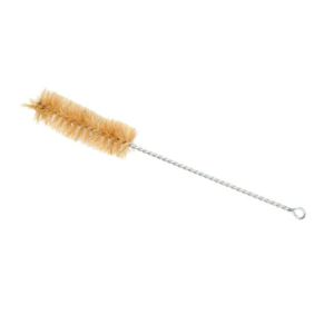
1.A.C. Single Phase .230 V. stabilized supply. 2.Floor Space -1.5 m X 1.5 m.Brush, Test Tube
XTEMOS ELEMENT
AJAX PRODUCTS TABS WITH ICONS
Burettes with Screw Type, PTFE Needle Valve Stopcock, Class ‘B’
Color Gauge Meter
Description
Color Gauge Meter Non-corrosive mounting hardware with weather resistant sealed lenses Superior quality internal components UV fade resistant race pointers Come with White Lights with Red removable cover Feature aluminum or plastic non-corrosive cases (automotive versions are steel) The AutoMeter Marine White Five Gauge Combination Kit is available in Standard or Monster Varieties and includes: 6000 RPM Tachometer Voltmeter Fuel Level Oil Pressure Water Temperature.Smart Energy Meter
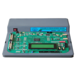
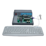
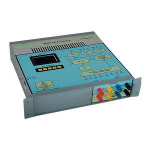
A Smart Energy Meter based on Analog Devices IC has been developed to build an Advanced Metering Infrastructure (AMI). The AMI system facilitates networking capability via GSM, ZigBee and ModBus. A Smart Energy Meter Development system has been developed by us, which consists of 1φ/3φ measurement section, a 32-bit ARM controller, wireless modules and powerful software. The student can completely understand the concept and usage of this trainer. This can be also used as one of the IOT server node.
Features
• 3 Phase energy readings displayed in the Graphics LCD • Simple design, Efficient and Highly Accurate • Easy connectivity for various loads • Keys to change the settings • Supports GSM, ZigBee and ModBus for networking • LPC2148 based processing board • 32/16 bit ARM7TDMI-S CPU with 60MHz maximum CPU clock • On board peripherals for extension • Graphics LCD interfaced to display the energy readings • Keys for various settings • Current Sensors and Voltage Sensors provided to measure 3 phase voltages and currents • Polyphase energy metering IC provides highly accurate energy measurement • Energy metering IC interfaced via I2C with Controller module • CC2530 Controller with maximum 32MHz CPU clock • High-speed and low-power 8051 CPU • 2.5GHz IEEE 802.15.4 compliant RF transceiver upto 250kbps data rate • UART Connectivity to interface with CPUDissolution Rate Test Apparatus
Specification
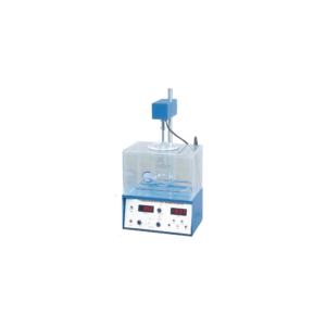
Consist of thermostatic control water bath which maintains temp. at 37DegC with + 0.5 Deg C variations. Provided with borosilicate vessel 1000 ml, variable speed motor, cylindrical wire mesh basket & shaft with blades of stainess steel. Single Basket, (Analog) Single Basket, (Digital R.P.M) Single Basket, (Digital) Temp. & R.P.MXTEMOS ELEMENT
AJAX PRODUCTS TABS LOAD MORE PAGINATION
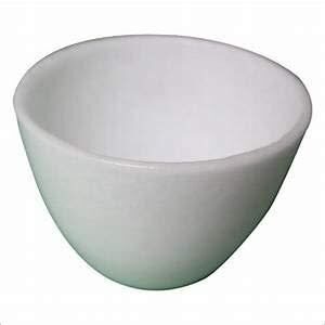
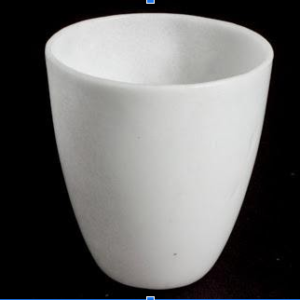
SILICA CRUCIBLE WITHOUT LID
PRODUCT DESCRIPTION
- Crucible is glazed inside and outside.
- Highly resistant to alkalis and hot temperatures
- 50ml capacity
- Outside diameter 55mm, 42mm height
- No lid includedSilica crucible is glazed inside and outside. Highly resistant to alkalis and hot temperature SIZES ARE: 15ML 25ML 50ML 80ML 100ML 150ML
SILICA CRUCIBLE TALL FORM Without Lid, Translucent
XTEMOS ELEMENT
