XTEMOS ELEMENT
AJAX PRODUCTS TABS
Drilling Tool Dynamometers
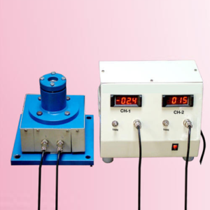
This is a armed wheel type strain gauge drill tool dynamometer designed to measure thrust and torque during drilling operation. This Dynamometer is suitable for drilling a hole up to 25mm size in mild steel. With this Dynamometer students can study the change in these force by varying speed, cut and feed
FEATURES:
1.Rigid in construction & Sensitive transuding and amplifying system for accuracy in force measurement. 2.Compact two channel digital force indicator. 3.Use of cutting fluid during operation is possibleSCOPE OF SUPPLY:
1.Mechanical sensing unit and work piece holder with strain gauges. 2.Control panel housing digital force indicator to measure both forces simultaneously, balancing potentiometer, connoting cables. 3.Necessary switches, fuses and screen printed front plate. 4.The dynamometer is calibrated at factory with help of proving ring and readings are directly in the from of kg.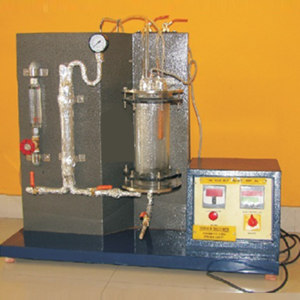
Critical Heat Flux Apparatus
The apparatus demonstrates the regimes of pool boiling. The test section consists of a test wire surrounded by water of constant temperature. The surface temperature of the test wire is heated by passing current through it. Due to the temperature difference between the wire surface and surroundings, the difference regimes are observed till the burnout point.
Specifications:
1.Test wire -35 gauge or 40 gauges. Length = 10cm. 2.Nichrome heater- 1 kw capacity – 1 nos. 3.Glass trough of sufficient capacity. 4.Table light to observe the test wire. 5.Voltmeter and ammeter to measure the input to the test wire. 6.Dimmerstat to adjust the voltage. A technical manual accompanies the unit.SERVICES REQUIRED:
1.220v, ISA, stabilized single-phase supply. 2.Floor surface- 1m x 1m at working height.
Light Dependent Resistor Unit (LDR)
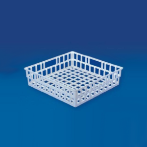
Draining Basket
We are known as the chief Exporter and Trader of the latest Draining Basket in India.
As the name suggests, the Draining Basket are available with wide net like structures on all sides.
These structures are proved really useful for draining different laboratory apparatus after washing them.
Made of polypropylene, Our Draining Basket can be repeatedly autoclaved.
| Particulars | Pack (Pcs) | |
|---|---|---|
| Draining Basket 400 x 400 x 100 mm | 6 |
XTEMOS ELEMENT
AJAX PRODUCTS TABS SIMPLE

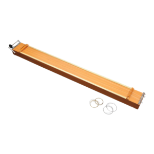
Sonometer, Two Wire
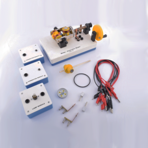
Motor Generator Model Set
Description
This motor-generator set gives students an insight into the physical and technical relationships on which electric motors, generators and transformers are based. The modular system allows to set up different function models without tools: Various DC motors Series and shunt motor Synchronous motor DC generator and alternator Transformer. This set allows the performance of 10 student experiments about the following topics: Magnetic field of a coil Conversion of electrical energy into kinetic energy Commutator Direct current motor Synchronous motor Series and shunt-wound motors Electromagnetic induction The electrical generator Engine-generator Transformer
Friction Board
XTEMOS ELEMENT
AJAX PRODUCTS TABS ALTERNATIVE
Fashion

Journal Bearing Apparatus
DESCRIPTION:
The apparatus consists of a plain steel shaft encased in a bearing and directly driven by a small electric motor. The bearing is freely supported on the shaft and sealed at motor end. The motor speed is precisely controlled by control unit and sealed at motor end. The motor speed is precisely controlled by control unit and can be run in both directions. The bearing contains twelve equi-spaced pressures tapping around circumference and four along the axis. All are connected by light flexible plastic tube to the manometer so that the pressure head of all sixteen point can be observed at a time. The bearing can be loaded by attaching weight to the arm supported beneath it.SPECIFICATIONS:
1. Journal : 50 mm. dia. (nominal) 2. Bearing : 55 mm. dia. 3. Weights : 4 adjustable weights 4. Motor : D.C. shunt Motor, 3,000 RPM. 5. Control panel : For speed control of Motor 6. Manometer panel : 16 tube Manometer 7. Oil recommended : SAE 10EXPERIMENTS:
1. Observation of the pressure profile at various conditions of load and speed. 2. Plotting the Cartesian and polar pressure curves. 3. Plotting the theoretical Summerfield curves.SERVICE REQUIRED:
1. Electric Connections : A.C Single Phase, 230v. supply with ear thing. 2. Stand Alone Space : 1.5m X 1.5m X 4m Height.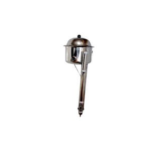
Distillation Plant (Manasty Type), Wall Hanging
The unit is recommended for making pyrogen fee distilled water of a very high degree of purity, Made out of S.S. special kettle element is fitted with Ejection Device / Auto cut for safety of the element is provided water supply is stopped.
The cork fitted to the unit is of brass C.P.A. wall Mounting clamp is provided with the unit.
Supplied with cord and plug to work on 220/240 volts A.C. Stainless Steel, Output approx. 3/4 Ltr./Hr.
Stainless Steel, Output approx. 5/6 Ltr./Hr.
Aluminium Dicasted, Output approx. 3/4 Ltr./Hr.
Aluminium Dicasted, Output approx. 5/6 Ltr./Hr.
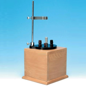
Aluminum Calorimeter, with wooden box
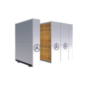
Mobile Insect Storage System
Description
An all new 'VERSATILE' space efficient, elegant looking, sturdy and compact system for insect storage supported with care, safety-privacy vis-a-vis being compact to accommodate large quantity in less space, easy to handle, convenient to monitor-sort. The system contains Compactor units which can be arranged to suite your requirements, according to the space available and above all can be secured with a single lock. The metallic compactor units made of mild steel with powder coated paint finish can be moved for handling the specimens and again joined to be locked only on the end unit and all units are secured. Showcases are arranged in rows of 20 each with two rows in each unit. End units are for 40 showcases whereas the intermediate units accommodate showcases back to back, i.e., 80 showcases and again the end unit for 40 showcases. Intermediate units can be increased as per space requirement. There are options for showcases, metallic or wooden. Size options of 53x45x7.5cm. or 45x45x7.5cm. or 45x30x6.5cm. with pinning EVA sheet is base, provision for insecticide, puller knobs, index card holder etc.XTEMOS ELEMENT
AJAX PRODUCTS TABS ARROWS PAGINATION
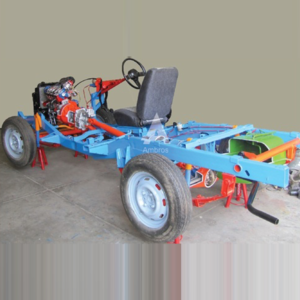
Car Chassis Rear Wheel Drive Actual Cut Section
Car Chassis Rear Wheel Drive Actual Cut Section – Motorised
4 Stroke 4 Cylinder Petrol Engine With Clutch, Gear Box, Propeller Shaft, & Rear Axle Assembly With Differential Gear
The chassis of the four stroke four cylinder engine cut section model. The cut section model is constructed such that all the following systems can be demonstrated in working conditions.
ENGINE
Maximum parts and accessories of an engine like cylinders, cylinder head, inlet and Exhaust manifolds, FIP, injectors, self-starter, alternator, water pump, radiator, etc., are sectioned to show the internal constructional details. The complete sectioned model is coupled with FHP 220/230V A.C single phase motor through a Reduction drive unit.TRANSMISSION SYSTEM:
This system consists of a Clutch and four speed gearbox assembly, the casing of which is suitably cut to demonstrate its operation. The gearbox is coupled to Differential gear box with propeller shaft and the different coupling used for this transmission can be demonstrated. The Differential gear box is also cut so as to clearly to demonstrate its complete operating principle. The gear shifting including the forward and reverse gear operation can be clearly shown. The speed variation and the rotation of the Differential gear box can be seen while gear shifting. By running the motor connected to the engine assembly the entire system with gear box, rear axle etc. can be demonstrated in running. FUEL SYSTEM: The Fuel tank is cut to expose the mounting of the level sensor and the position of Fuel section. The system is complete with mechanical Fuel pump. EXHAUST SYSTEM:It consists of Exhaust Manifold and silencer in cut section to explain internal construction. LUBRICATION SYSTEM: It consists of the engine Lubrication system along with the Lubrication oil pump is suitably sectioned. SUSPENSION SYSTEM: This will explain both the Hydraulic Suspension systems at the front and the leaf spring Suspension at the Rear. One of the hydraulic arrangements of Suspension mechanism is highlighted (with shock absorbers) and explained cut sectionally.BRAKING SYSTEM:
The Hydraulic or Air circuit Brakes. The movement of the Brake Shoes on operating the brake pedals can be seen in the area where the Brake drum is cut. The front and rear brakes will be operational. STEERING MECHANISM: The can be seen and included in the Steering wheel. Steering gear box and coupling of the same to the wheels will be shown by rotating the steering wheel, the operation of the steering system can be demonstrated. The entire system will be mounted on the chassis, and suitable mounting option with caster wheels will be provided for easy movability.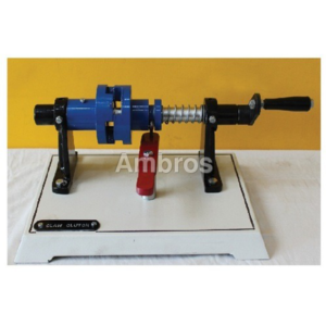
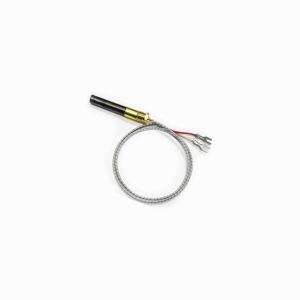
Thermopile
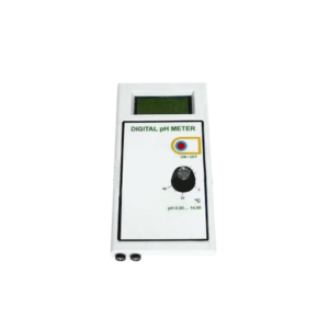
pH Meter, Digital, Portable
Highly stable and accurate.
Digital display.
Technical Specification
Display: 3½ digit LCD Range: pH : 0 to 14.00 Resolution: pH : 0.01 Accuracy: pH : ±0.01 Compensation: Manual 0 to 100° Slope Correction: 80 to 120% Power: 1 x 9V Battery Dimensions: 85 x 28 x 165 mmAccessories
Combination pH Electrode Operation ManualXTEMOS ELEMENT
AJAX PRODUCTS TABS WITH ICONS

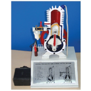
2 Stroke Petrol Engine Sectional Working Model
XTEMOS ELEMENT
AJAX PRODUCTS TABS LOAD MORE PAGINATION
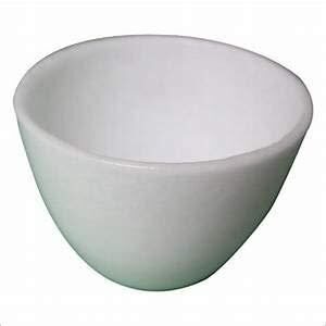
SILICA CRUCIBLE WITHOUT LID
PRODUCT DESCRIPTION
- Crucible is glazed inside and outside.
- Highly resistant to alkalis and hot temperatures
- 50ml capacity
- Outside diameter 55mm, 42mm height
- No lid includedSilica crucible is glazed inside and outside. Highly resistant to alkalis and hot temperature SIZES ARE: 15ML 25ML 50ML 80ML 100ML 150ML
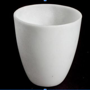
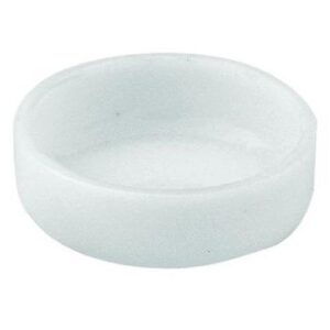
SILICA CRUCIBLE TALL FORM Without Lid, Translucent
XTEMOS ELEMENT
AJAX PRODUCTS TABS CAROUSEL
6 Axis Robotic Trainer
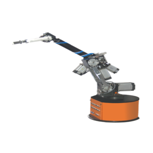
For beginners this kit is very useful to learn the concept and working. For experienced, this kit helps to make new ideas. This kit is used to study the ROBO characteristics of arm movement. Each axis has one stepper motor. Gripper has one miniature cylinder to pick and place the object. Software controls the ROBO arm and measures the motor axis and arm axis. Simplicity of this kit makes maintenance easier and friendly to user. This kit is very flexible to operate and easy to move.
Features
• Easy to learn • New design • Easy for maintenance • Drive by stepper motor • Easy to programSpecification
• Arm : Jointed Arm • Axis : 6 • Motor : Stepper Motor • Gripper : Pneumatic • Drive : Stepper Motor Drive • Controller : MicrocontrollerBase
• Angle of movement : 320º • Gear Type : Spur Gear • Position Detector : Limit SwitchIntermediate ARM
• Angle of movement : 90º • Gear Type : Spur Gear, Worm Gear • Position Detector : Limit SwitchVertical ARM
• Angle of movement : 90º • Gear Type : Spur Gear • Position Detector : Limit Switch
Draining Rack
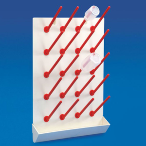
Draining Rack provides an excellent option for post wash draining of tubes & bottles in the laboratory.
The back plate of this Draining Rack has 20 holes into which pegs are tightened with the help of screw-nuts.
Bottom of the rack is provided with a tray which collects all the waste water drained down which can further be collected in a container via drain tube.
This rack not rot, stain or rust.
Material : Acrylopitrile Butadiene Styrene / Polycarbonate
| Particulars | Pack (Pcs) | |
|---|---|---|
| Draining Rack | 1 |
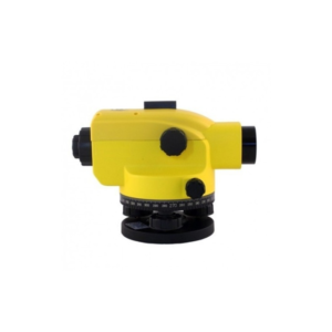
Automatic Level
Description
a) Manufactured meticulously using International Standard. b) Tightly sealed construction for use in any weather. c) Fast accurate two-speed focusing. d) Friction-braked rotation and endless horizontal drive. e) Optical sight for quick pointing. f) Metal circular bubble. g) Fit all tripod with G5/8" or M16 screw.Optional accessories :
Metal or wooden tripod, metal or wooden staff range pole, measuring rope, plumb etc