XTEMOS ELEMENT
AJAX PRODUCTS TABS
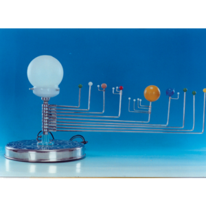
Solar System Model
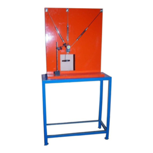
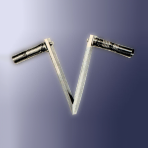
Pinned Joint Model
SPECIFICATION:
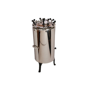
Model consists of hinged. Model will be able to demonstrate the qualitative behavior of the truss under load. As are very flexible, a compression members will easily it`s bucking i.e. It will curve of plain. The tension member however remains straight and tight. The student will therefore have a visual picture of the type of stresses i.e. Compressive or tensile that member of truss will carry under various positive of the load. In case of pinned joint truss, the student will be able to observe that angle between members at each joint undergo a small change.Autoclave Vertical Sterilizer
Specifications
Made of stainless steel with the inner chamber of a thick pressure gauge. The outer surface has a mirror polish. The lid of this autoclave is thick along with a safety valve, pressure release valve, and drain valve. Spring loaded valve to adjust the pressure. Works on 220V AC. Radial or wing nut type door locking. Digital temperature indicator. Water level indicator.| Dimension | Power | Capacity | |
|---|---|---|---|
| 250x450mm | 2KW | 22litres | |
| 300x500mm | 3KW | 40litres | |
| 350x550mm | 4KW | 50litres | |
| 400x600mm | 5KW | 75litres | |
| 450x600mm | 5KW | 95litres | |
| 550x750mm | 6KW | 187litres |
XTEMOS ELEMENT
AJAX PRODUCTS TABS SIMPLE
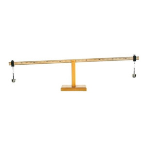
Wooden Lever Apparatus
Made of wood, one meter long graduated scale is balanced on knife edge of the fulcrum. Supplied with 2 sets of 100 g weights.
One meter long with fulcrum lever is graduated in centimeters and is balanced on the fulcrum by a transverse groove cut midway in the length of the lever over knife edge of the fulcrum, supplied with 2 sets of 100 g weights.
Thermocouple, Single
XTEMOS ELEMENT
AJAX PRODUCTS TABS ALTERNATIVE
Fashion
Open Wind Tunnel Apparatus
Technical Description
A wind tunnel is the classic experiment system for aerodynamic flow experiments. The model being studied remains at rest while the flow medium is set in motion, and thus the desired flow around the model is generated. Open wind tunnel used to demonstrate and measure the aerodynamic properties of various models. For this purpose, air is drawn in from the environment and accelerated. The air flows around a model, such as an aerofoil, in a measuring section. The air is then decelerated in a diffuser and pumped back into the open by a fan. The carefully designed nozzle contour and a flow straightener ensure a uniform velocity distribution with little turbulence in the closed measuring section. The flow cross section of the measuring section is square. The built-in axial fan with guide vane and a variable-speed drive is characterised by an energy-efficient operation at high efficiency. Air velocities of up to 28m/s can be reached in this open wind tunnel. The trainer is equipped with an electronic two-component force sensor.Lift and drag are detected and displayed digitally. The air velocity in the measuring section is displayed on the inclined tube manometer. The tube manometers is recommended for measuring the pressure curves in drag bodies. Extensive accessories allow a variety of experiments, for example lift measurements, pressure distributions, boundary layer analysis or visualisation of streamlines. The well-structured instructional material sets out the fundamentals and provides a step-by-step guide through the experiments.Learning Objectives & Experiments
– Determine drag and lift coefficients for different models – Pressure distribution when flowing around drag bodies – Boundary layer analysis – Investigation of flutter – Wake measurementFeatures
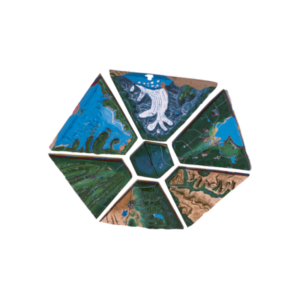
* Open wind tunnel for a variety of aerodynamic experiments * Homogeneous flow through the flow straightener and special nozzle contour * Transparent measuring sectionLandform Model
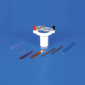
Voltaic Cell Set, Student
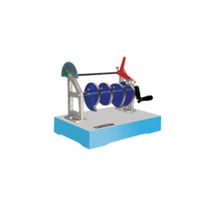
Action of Cams
XTEMOS ELEMENT
AJAX PRODUCTS TABS ARROWS PAGINATION
Cold Chisels
XTEMOS ELEMENT
AJAX PRODUCTS TABS WITH ICONS
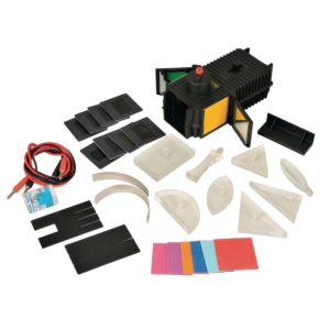
Light Box and Optical Set
Description
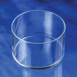
A Robust light box in matt black finish with a 12 V 24 W axial filament lamp with flexible leads. One end of the box takes a cylindrical convex lens in an adjustable sliding mount to enable production of convergent, parallel or divergent beams. Complete with accessories which consist of: 5 Plastic blocks, one rectangular, One semicircular, One equilateral prism 60° x 60° x 60°, One right angle prism 90° x 60° x 30° and one right angle prism 90° x 45° x 45°. 3 Cylindrical acrylic lenses: one double convex, one double concave, both having the same radius of curvature and one thick convex lens. 3 Mirrors, one plane glass, one curved parabolic and one curved semi-circular. 2 Slit plates, one with three narrow and one narrow slits, the other with four narrow and one wide slits 1 Set of eight colour filters, Red, Green, Blue, Cyan, Violet, Yellow, Orange and Magenta. 1 Set of coloured cards, Red, Green, Blue, Violet, Orange, Cyan, Yellow and Pink. Complete with one spare lamp, in box.PNEUMATIC TROUGH
PRODUCT DESCRIPTION:
Use a circular Glass Circular Pneumatic Trough made of soda lime glass to conduct gas analysis experimentation in the laboratory. A secondary use is for specimen storage
Features:
- Circular soda lime glass
- For collection of gases over water
- Three sizes
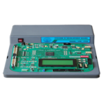
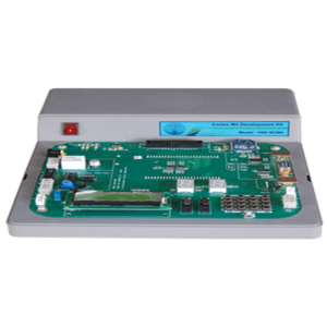
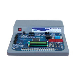
Xilinx Spartan 3E FPGA Trainer Kit
Specification
• XC3S250E - 4PQ208C / XC3S500E-4PQ208C • 16 Nos. of digital input using slide switches with LED indication • 16Nos. Of digital outputs using discrete LEDs • 16 x 2 LCD is provided for display the text message. • One Reset Switch • One switch is provided for giving manual clock • FPGA configuration through - JTAG Port - On board Flash Prom XCF02S • Total 158 I/O pins : 124 pins used for integrating peripherals like LED, Switches etc., balance pins available to user in 20 pin • header (3.3V compatible) • 1No of 26pin header to interface VLIM cards like Traffic Light Controller (5V compatible) • On board programmable PLL oscillator from 1 MHz to 100 MHz using jumpers • 4 Nos of 7 segment LED display • One relay and Buzzer provided. • Stepper & DC motor Driver provided. • 4 * 4 matrix key provided • Housed in a sleek plastic cabinet with built in SMPS 5V/2A. • Compatible with Xilinx ISE Design Suite WebPACK Software. • On board USB to JTAG is available for configure FPGA (Supports only with Vi JTAG 5.0 Software)XTEMOS ELEMENT
AJAX PRODUCTS TABS LOAD MORE PAGINATION
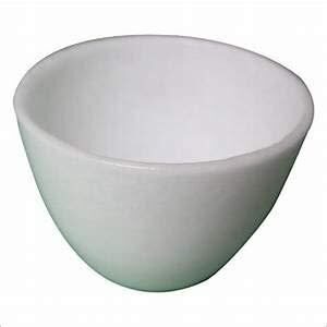
SILICA CRUCIBLE WITHOUT LID
PRODUCT DESCRIPTION
- Crucible is glazed inside and outside.
- Highly resistant to alkalis and hot temperatures
- 50ml capacity
- Outside diameter 55mm, 42mm height
- No lid includedSilica crucible is glazed inside and outside. Highly resistant to alkalis and hot temperature SIZES ARE: 15ML 25ML 50ML 80ML 100ML 150ML
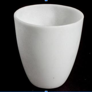
SILICA CRUCIBLE TALL FORM Without Lid, Translucent
XTEMOS ELEMENT
