XTEMOS ELEMENT
AJAX PRODUCTS TABS
Demonstration Gear Model System
Description
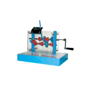
A series of models to demonstrate different gearing systems. With transparent slideplates, the gears may easily be seen and where necessary there is an index on the primary and secondary shafts to show the change in the direction of rotation and the relative speed of rotation. A simple three-speed and reverse-gear system using spur gears. Reverse gear is obtained by interposing a small lay-shaft mounted pinion between the two main shafts. Gear selection is by means of a short ball-ended lever.Analog PID Controller
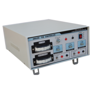
The analog PID controller is a special purpose analog controller with operational amplifiers The controller permits a detailed analysis of the application of proportional, integral and derivative control to the improvement of their performance. The controller may be used at high speed for oscilloscope observation or at a low speed for meter observation.
FEATURES:
• Two analog meters (centre zero meters) to display the set variable and process variable. • In built regulated power supply. • Provision to vary and measure the setpoint (0-5)V • Provision to vary the proportional gain, Integral time and derivative gain. • Provision to give either (4-20)mA or (0-5)V externally as a process variable. • Provision to select the controller output as (4-20)mA or (0-5)V internally. • All the components are mounted in an attractive cabinet. • Interface with any realtime process (Level, Flow, Temperature, Pressure, DC motor speed control etc.,)Bar & Gauge
XTEMOS ELEMENT
AJAX PRODUCTS TABS SIMPLE
Newton’s Color Disc
Description
To demonstrate the discovery made by Newton that white light is composed of seven colors. Consisting of a pulley mounted on a metal stand, the seven colored disc is driven by gears connected to a hand driven wheel. When the colored disc rotates, the eye can’t distinguish between individual colors and perceive it as white color.10KW IGBT Based Power Module
FEATURES:
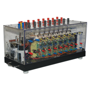
• 1200V/ 75A, Peak Semikron based IGBT module • 8 Nos of IGBT’s provided with independent eight driver (inbuilt opto isolator) • All the collector and emitter terminals are brought out of proper connectors for power circuit connection • All the gate and emitter terminals are brought out and terminated on front panel to view driver output fault output • Indicator LED provided for PWM input and power supply input • Proper heat sink provided for all the IGBTs with cooling fan provision • All are enclosed by viewable acrylic cabinet • Temperature sensor provided for over temperature Protection • PWM inputs are brought out on Front Panel, you may connect any controller for interface • One common +15V Power supply for all the driver circuit, Inbuilt isolated power supply provided. • Over current protection and short circuit protection provided for all individual IGBT module • Reset circuit provided and terminated to clear the fault • Snubber capacitor provided for dv/dt protection for all IGBT module • 60A 3 phase bridge rectifier and filter circuit available for power circuit input.Desert Cooler Trainer
Desert Cooler Trainer works on the principle of evaporative cooling. It is used mostly in the dry hot regions; it consists of a fan which sucks the air from atmosphere through the pads which are used in desert coolers very frequently. The difference in DBT & WBT at inlet and outlet can be measured hence the RH from the charts. Also the amount of water evaporated can be calculated by knowing the water level difference in the reservoir.
SPECIFICATIONS:
1.Fan connected to 1/2 HP motor. 2.Air Cooler Pump to circulate water. 3.DBT & WBT Measuring Thermometer at inlet and outlet. 4.Orifice meter with manometer to measure the air flow. A technical manual accompanies the unit.SERVICES REQUIRED:
1.Floor Area – 1, X 1 m. X 1 -5m. Height. 2.220 V., 15 Amp. , Single Phase Stabilized power supplyRules Steel
XTEMOS ELEMENT
AJAX PRODUCTS TABS ALTERNATIVE
Fashion
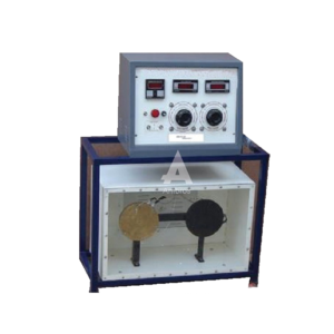
Emissivity Measurement Apparatus
The apparatus consists of a test plate and a comparator. A black plate is used as a comparator for test plate. When all the physical, dimensions and the temperatures are equal, heat losses from both plates will also be the same, except radiation losses. Hence the input difference will be due to difference in emissive. Both the plates are kept in a panel enclose with perplex front and are given inputs through separate dimmerstats so that temperatures of both can be kept equal. Thus emissivity can determine over a wide range of temperatures.
SPECIFICATIONS:
1.Test plate and Black plates — 160mm. Dia. Aluminum plates, mounted in Panel with mica heater inside. 2.Instrumental panel consisting of- a)Voltmeter and ammeter for input measurement to both heaters through a selector switch. b)Separate dimmers for both the plates. c)Multichannel digital temperature indicator. A technical manual accompanies the unit.SERVICES REQUIRED:
1.Space area of 1.5m x 1 m. at working height. 2.230v, 15A, AC supply with earthing connectionElectric Motor St. Louis
Description
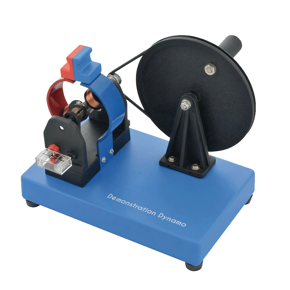
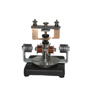
The motor consists of a two pole armature mounted between the ends of two bar magnets. The armature has a two section commutator and a pair of slip-rings on its shaft and is so constructed that the wire cannot slip off the iron core. The upper bearing and brushes for the commutator are mounted on a strong upright. Separate brushes are provided for the commutator and for slip rings and each are connected to a terminal. The magnets are held in position by thumb screws.Transaxle Gear Box With Differential
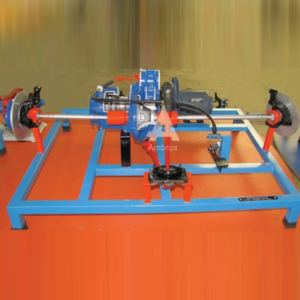
Transaxle Gear Box With Differential – 4 Forward & 1 Reverse Actual Cut Section
The working of gear box is shown with the help of actual parts assembled on square iron pipe frame. All the necessary parts of gear box are shown in actual working form. This model helps the student to understand the working of the gear box very easily. It is specially made dissectible for demonstration purposes.
PAM-PPM-PWM Modulation and Demodulation Trainer
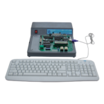
PAM- PPM- PWM is the basic pulse modulation techniques. This trainer provides complete setup to the students for performing Experiments on these techniques. They can study Sampling, Pulse Modulation &Signal reconstruction process. Separate circuits are provided for each Techniques.
FEATURES:
• PAM- PPM- PWM Modulation and Demodulation Techniques,using Natural and Flat - top Sampling. • Natural Sample, Sample and Hold and Flat-top outputs. • Selectable 2 different sampling pulse frequencies on board. • On board Sine wave generators. • Voice communication using dynamic microphone and speaker • On board Filters and Amplifier • Functional blocks indicated on board schematic • Input- Output and Test points provided on board. • Built in DC Power Supply • Fully documented operating ManualTECHNICAL SPECIFICATION:
• Crystal Frequency : 6.14MHz • Sampling Frequency : 16 KHz, 32 KHz • Sine wave Generator : 1 KHz &500Hz, Amplitude (0-5)V, Tolerance +5% • Low Pass Filter : 4 Order BW Filter • Cut off frequency : 3.4 KHz • Voice Communication : Voice Link using dynamic mic& speaker • AC Amplifier : With Adjustable Gain control • Microphone type : Dynamic, 600 Ohm. • Audio Pre-amplifier : Op-amp based • Power amplifier : 1W Mono • Interconnections : BS2 Connector. • Power : 230V, 50HzXTEMOS ELEMENT
AJAX PRODUCTS TABS ARROWS PAGINATION
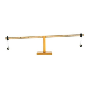
Wooden Lever Apparatus
Made of wood, one meter long graduated scale is balanced on knife edge of the fulcrum. Supplied with 2 sets of 100 g weights.
One meter long with fulcrum lever is graduated in centimeters and is balanced on the fulcrum by a transverse groove cut midway in the length of the lever over knife edge of the fulcrum, supplied with 2 sets of 100 g weights.
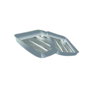
Dissecting Trays
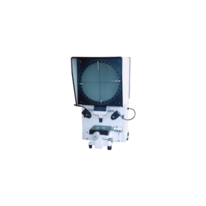
Profile Projector 300mm Dia
Specifications
300mm dia 360 degree rotatable graduated screen with venire and 90 degree cross hair line providing high accuracy of linear and angular measurements, providing illumination of contour lamp 12V/100W and two surface (12v/35W) lamps, with three standard magnifications.
Standard Features:
| X-Y Bed Size | : | 150mm X 150mm, fitted with hard steel balls for X-Y movement | |
| Travel X-Y movement (Standard) | : | 50 X 50mm | |
| Micrometers (50mm Dia) | : | Zero Adjustable 25mm (L.C 0.01mm) | |
| Angular Measurement | : | Manual, 360 degree graduated ring with 1 minute venire | |
| Maximum size of object view | : | 28mm (dia) | |
| Max Working Distance | : | 65 mm | |
| Standard Magnifications | : | 10x, 20x & 50x |
XTEMOS ELEMENT
AJAX PRODUCTS TABS WITH ICONS
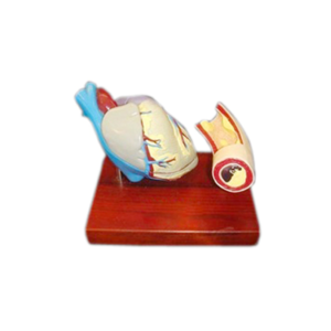
Heart With Artery Blockage Models
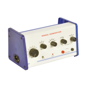
Signal Generator
Audio frequency Generator is versatile instrument providing sine, square & triangular wave functions over a wide range from 2 220 KHz in decade ranges. The amplitude of the waveforms can be varied from 20 mV to 20 V peak to peak about zero level with the help of three step coarse control & fine control. The complete unit is enclosed in an attractive metal cabinet.
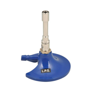
Burner Bunsen – Semi Micro
XTEMOS ELEMENT
AJAX PRODUCTS TABS LOAD MORE PAGINATION
SILICA CRUCIBLE WITHOUT LID
PRODUCT DESCRIPTION
- Crucible is glazed inside and outside.
- Highly resistant to alkalis and hot temperatures
- 50ml capacity
- Outside diameter 55mm, 42mm height
- No lid includedSilica crucible is glazed inside and outside. Highly resistant to alkalis and hot temperature SIZES ARE: 15ML 25ML 50ML 80ML 100ML 150ML
SILICA CRUCIBLE TALL FORM Without Lid, Translucent
XTEMOS ELEMENT

