XTEMOS ELEMENT
AJAX PRODUCTS TABS
CNC Mill Trainer
CONTROLLER:
SIEMENS 802D Main Spindle Drive : D.C. Thyristor Drive, Inbuilt Safety, 1.5 HP X, Y and Z Drives : SIEMENS Servo Motors and Drives Input to Stepper : Optically lsolated Motor Drive TTL compatible Interpolation : Linear, Circular parabolic Interpolation, Slot / Pocket Milling Code Used : G, M, S, T, F, I, K, M, F, Cycles : Circular Interpolation, Mirror, Pocket Milling Cycle Pocket & Helical Milling : Provided with Std CodesTABLE:
Length x Width : 450 x 175 (approx.) Clamping Area : 350 x 175 (approx.) T Slots : 10mm slot widthMACHINE DETAILS:
Resolution : 5 micron Tool Change : Automatic, 8 station Rapid Travel : 5000mm/min Weight in kg : 750kg Dimension in mm : 850 x 850 x 1550 mm Automatic Lubrication : Provided Repeatability : 10 micronSPINDLE:
Spindle Speed : Continuous Variable Spindle power : 1.5 HP Inside Taper : ISO 30 Speed Range : 100 to 4000 RPMAXIS TRAVEL
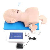
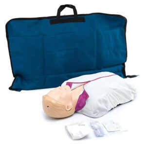
Longitudinal Traverse : 250mm Cross Traverse : 175mm Vertical Traverse : 250mmCPR Training Manikins(torso)
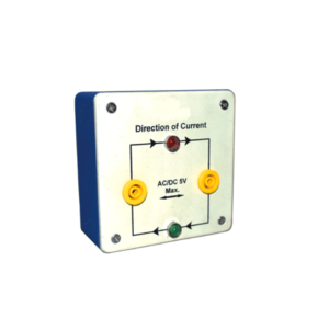
Direction of Current
XTEMOS ELEMENT
AJAX PRODUCTS TABS SIMPLE
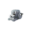
Rocking Microtome
Description
A sectioning equipment, economical and simple, yet providing all facilities of a standard rotary microtome. The internal mechanism is fully enclosed in a sturdy metal case, for protection against dust and grit & is driven by a handle which can be locked in position. A ball & socket type movement permits use of the entire knife edge. With a feed range of 1 to 25 microns in steps of 1 micron. Supplied complete with a set of three object holders, one razor 120 mm with back and handle, one honing plate, one bottle of oil for lubrication, dust cover and wooden cabinet.Abney Level
Description
The Hand Level is a small, economical level for use with preliminary surveys to determine traveller way or cable way steel work elevations and other feasibility type site reconnaissance work. The Abney Level is very similar to a clinometer in that it is used to measure the value of a slope by means of arc measure and grade percentage.Specification of Abney Level
• Used to determine slope angle, tree heights etc • Graduated 0-+/-90 degrees, 0-+/-100% on a stationary arc • Vernier reads to 10 • Scale pointer incorporates friction thumb lock • Includes carry caseSpectrometer, Advanced
Description
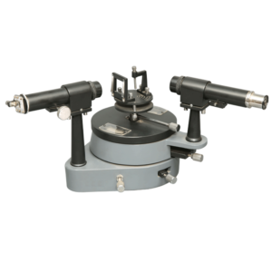
Vernier reading to 30 seconds of arc. The 175 mm diameter scale is fixed. The table and telescope movements are completely independent of each other and read to 30 seconds of arc by means of double ended verniers and magnifiers. Both rotations have fine adjustment screws. Coarse adjustments can also be made by release of clamping screw. Collimator is mounted on a fixed pillar and is fitted with 175 mm fl. achromatic objective with 32 mm clear aperture and a laterally adjustable slit 6 mm long. Telescope is mounted on a movable pillar fitted with 175 mm fl. achromatic objective of 32 mm clear aperture and x 10 Ramsden eye-piece with a glass cross line graticule. Both the telescope and collimator have rack and pinion focusing and can be adjusted for leveling the axes of both units as well as for adjusting to the axis of rotation. Prism table is marked with lines to assist prism placement and has three table leveling screws. It also has an interchangeable clamping unit for the prism and diffraction grating. Complete with prism clamp, diffraction grating holder and a Tommy bar for adjusting optical axis, In case.Study of Operation Amplifier
XTEMOS ELEMENT
AJAX PRODUCTS TABS ALTERNATIVE
Fashion
Theramal Conductivity Of Insulating Slabs
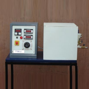
The apparatus consists of a slab assembly. The main Heater and a radial guard heater are sandwiched between copper plates. The specimen in the form of slabs of equal thickness are placed on either sides of heaters and cooling plates through which water is circulated are on the other Sides of the specimen. The radial guard heater ensures all heat of the main heater to pass axially through the specimens which is collected by cooling plates. By knowing the temperatures and Heat input, thermal conductivity of specimen can be calculated. The test set up is enclosed in an enclosure with insulation inside to provide undisturbed Surroundings. The design style of the apparatus is similar to as recommended in INDIAN standard. The difference is in sizes.
SPECIFICATIONS:
1.Heaters: a)Main heater plate 110 mm dia. with mica heater Sandwiched between copper plates. b)Radial guard heater plate I.D. 120mm and OD 200 mm mica heater sandwiched between copper plates. 2.Water circulated cooling plates -2 nos. 3.Dimmerstat-2 A capacity – 2 nos. to independently control Inputs to the heaters. 4.Measurements – A voltmeter and an Ammeter with selector switches to measure inputs,Multichannel digital temperature indicator to measure Temperatures at various points, having 0.1 °c least count. A technical manual accompanies the unit.SERVICES REQUIRED:
1.230 V, A.C. stabilized supply along with earthing connection. 2.Water supply of about 4-5 lit/min. 3.Bench area 1m x lm x O.5m height.Decade Inductance Box – 3 Dial
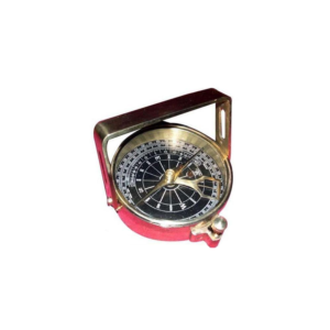
Clinometer Compass
Description
Clinometer Handle Compass is a reproduction of an antique Clinometer compass. The Handle Compass gets its name from its "handle" shaped sight, which actually serves two purposes With the compass level, an object can be viewed through the peep sights to determine its magnetic heading. The second and most interesting purpose is when tilting the compass on its side and viewing an object through the sights, its angle of elevation or declination can be found. A weighted pendulous arm beneath the compass needle can be read from one of three scales : Angle in degrees beneath the zenith (from straight up), angle in degrees of elevation or declination, and in inches per yard of slope. The compass has a needle lift mechanism to protect the compass jewel and the pendulous arm when being transported.XTEMOS ELEMENT
AJAX PRODUCTS TABS ARROWS PAGINATION
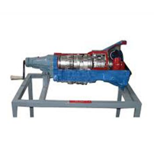
Gear Box Actual Cut Section
Gear Box – Actual Cut Section
The working of gear box is shown with the help of actual parts assembled on square iron pipe frame. All the necessary parts of gear box are shown in actual working form. This model helps the student to understand the working of the gear box very easily. It is specially made dissectible for demonstration purposes.
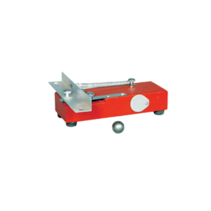
Falling Body Apparatus
L-Section launcher with holes for locating two 19mm.
diameter steel balls which act as projectiles.
Launcher is released by push button and projects one ball forward while allowing the other to fall freely Launching mechanism mounted on wooden block, 180x60x30mm.
which may be clamped by bench and has a convenient storage pocket for the balls.
Complete with two steel balls.
XTEMOS ELEMENT
AJAX PRODUCTS TABS WITH ICONS
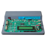
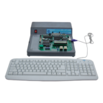
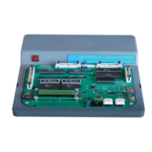
8086 Microprocessor Trainer Kit
Specification
• INTEL 8086CPU AT 4.77 MHZ CLOCK SPEED • 16KB for monitor EPROM upgradable to 64kb • 16KB RAM expandable to 64KB • Battery backup provision for RAM upto 64KB • 16 x 2 (or) 20 x 4 Alphanumeric LCD display • 101 keys IBM compatible keyboard • 24 TTL I/O lines brought out to two nos., of 26 pin FRC connector • 1 number of standard RS232C compatible serial port brought out to a pin D type male connector. • 3 channel 16 bit counter/timer using 8253. • Fully buffered address data and control signals terminated at a 50 pin header(VXT BUS) for interfacing VBMB series • of experiment boards and bus expansion. • 8 no’s of interrupt lines are terminated at a 10 pin connector. • Kit operates with a single +5V/DC supply • The kit and the power supply are mounted on a attractive light gray color fiber glass cabinet with fiber glass top cover. • Built-in line assembler & Disassembler • Powerful debugging monitor to develop user program.Lathe Tool Dynamometers
This is a strain gauge type two component lathe tool dynamometer designed to measure vertical and horizontal forces on the while orthogonal cutting process. The unit is in two parts one is mechanical sensing unit or tool holder, which can mounted on the top of the Ross slide after removing swivel base and compound slide of a lathe and digital force indicator. With this Dynamometer student can study the change in these forces by varying Speed, Cut and Feed.
FEATURES:
1.Rigid in construction 2.Sensitive transuding and amplifying system for accuracy in force measurement. 3.Compact Digital force indicator. 4.Use of cutting fluid during operation is possible.SCOPE OF SUPPLY:
1.Mechanical sensing unit or Tool Holder with string gauges. With H.S.S. tool of ½ “ size. 2.Control panel housing digital force indicator to measure two forces simuletensiously, balancing potentiometers, connoting cable. 3.Necessary switches, fuses and polycarbonate front plate. Range o to 500 Kg. 4.Centre Height, P.C.D.of clamping bolt size, clamping Bolt size. Three component lathe tool dynometer is also available.XTEMOS ELEMENT
AJAX PRODUCTS TABS LOAD MORE PAGINATION
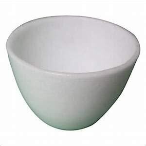
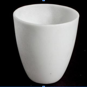
SILICA CRUCIBLE WITHOUT LID
PRODUCT DESCRIPTION
- Crucible is glazed inside and outside.
- Highly resistant to alkalis and hot temperatures
- 50ml capacity
- Outside diameter 55mm, 42mm height
- No lid includedSilica crucible is glazed inside and outside. Highly resistant to alkalis and hot temperature SIZES ARE: 15ML 25ML 50ML 80ML 100ML 150ML
SILICA CRUCIBLE TALL FORM Without Lid, Translucent
XTEMOS ELEMENT
