XTEMOS ELEMENT
AJAX PRODUCTS TABS
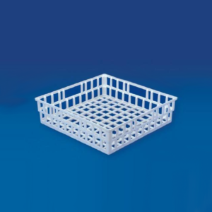
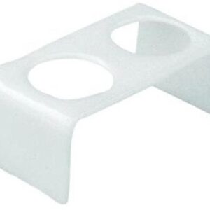
Draining Basket
We are known as the chief Exporter and Trader of the latest Draining Basket in India.
As the name suggests, the Draining Basket are available with wide net like structures on all sides.
These structures are proved really useful for draining different laboratory apparatus after washing them.
Made of polypropylene, Our Draining Basket can be repeatedly autoclaved.
| Particulars | Pack (Pcs) | |
|---|---|---|
| Draining Basket 400 x 400 x 100 mm | 6 |
Special Human Physiology Charts
Description
Poly art Charts are multi colored, accurate in details, printed on plastic, laminated on both sides, washable, non-tearable and long lasting, with plastic rollers, size 75 x 100 cm.The Lymphatic System
Excretory System – Kidney, L.S. Excretory System – Ureters Excretory System – Urinary bladder Excretory System – Malpighian Corpuscle T.S. Skin Reproductive System Brain External Features L. S. Eye – Eye Muscle L. S. Eye – Tear glands L. S. Eye – Physiological diseases of eye Ear and its parts Skeletal System Endocrine glands Digestive System Circulatory System – Types of blood cells Circulatory System – L. S. in heart & T. S. in blood vessel Circulatory System – Vein valves Circulatory System – Systematic & pulmonary circulation Respiratory System – Larynx Respiratory System – Trachea Respiratory System – Alveolus L. S. in Central Nervous System (CNS) Region in which the nerves impulses transport to central nervous system through the synapse Human Reflection Arch
XTEMOS ELEMENT
AJAX PRODUCTS TABS SIMPLE
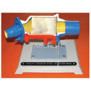
Catalytic Converter Actual Cut Section
The working of catalytic converter is shown with the help of actual parts assembled on iron base. All the necessary parts of catalytic converter are shown in actual working form. This model helps the student to understand the working of the catalytic converter very easily. It is specially made dissectible for demonstration purposes.

Critical Heat Flux Apparatus
The apparatus demonstrates the regimes of pool boiling. The test section consists of a test wire surrounded by water of constant temperature. The surface temperature of the test wire is heated by passing current through it. Due to the temperature difference between the wire surface and surroundings, the difference regimes are observed till the burnout point.
Specifications:
1.Test wire -35 gauge or 40 gauges. Length = 10cm. 2.Nichrome heater- 1 kw capacity – 1 nos. 3.Glass trough of sufficient capacity. 4.Table light to observe the test wire. 5.Voltmeter and ammeter to measure the input to the test wire. 6.Dimmerstat to adjust the voltage. A technical manual accompanies the unit.SERVICES REQUIRED:
1.220v, ISA, stabilized single-phase supply. 2.Floor surface- 1m x 1m at working height.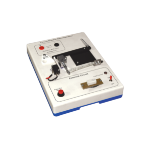
Circuit Breaker Demonstration
Description
Investigate the working principle of circuit breaker type fuse with this demonstration model. The apparatus is built on a robust plastic base and includes resistive loads to simulate external wiring circuits. Applications of the thermal response of bimetal strips and also electromagnetism (movement from a solenoid) are clearly demonstrated in this model. When a 12 V DC supply is connected (not supplied) the LED lights to show that current is flowing in the external circuit and the bi-metal strip can be seen to bend as its heater coil raises the temperature. After a few minutes the bending is sufficient to trip the mechanism and the current path is broken. At any current selection a short circuit situation can be initiated by pressing the red button and this produces an immediate response from the solenoid to disconnect the supply.
Scintillation Vial
We provide an impressive range of Scintillation Vial to our clients.
These unbreakable vials, molded in Polyethylene, are fitted with leak proof screw caps.
These Scintillation Vial can be used with standard counting equipment for liquid scintillation system.
Fabricated from high grade components, Scintillation Vial is excellent for low activity count.
Material : High Density Polyethylene
| Particulars | Pack (Pcs) | |
|---|---|---|
| Scintillation Vail 8 ml | 100 | |
| Scintillation Vail 20 ml | 100 | |
| Rack For 90 Vails of 8 ml Scintillation Vail | 2 | |
| Rack For 50 Vails of 20 ml Scintillation Vail | 2 |
XTEMOS ELEMENT
AJAX PRODUCTS TABS ALTERNATIVE
Fashion
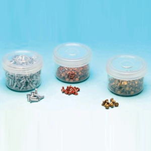
Metal Rivets, Brass
Description
Supplied as rivets. Pk of 500gms. Brass,lead,aluminium,iron, For specific heat capacity experiments. Supplied as rivets. Packets of 500 grams.300 mm long x 3 mm dia. Supplied in packets of ten rods. Copper,iron,lead,aluminium,brass 300 mm long x 3 mm dia. Supplied in packets of ten rods.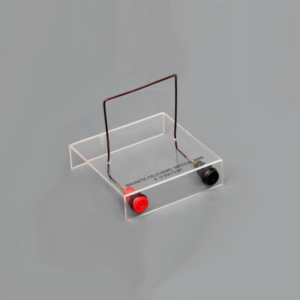
Magnetic field demo, vertical wire
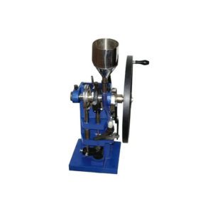
Tablet Making Machine (Hand Operated)
Details
Single punch automatic compression and injection device with each revolution of the wheel drive automatic feed and remove of tablets. Built on heavy cast body with centric pressure system SS hoper provided and connected by a rubber tube easy setting for thickness and hardness of tablets with nuts and locknuts.Features
Easily rotating wheel for making tablets. Compressing lever for adjustable harness of tablets. Adjustable lower punch for adjusting the thickness. Stainless steel day and punch size 6, 9, 12 mm. Electrical model can be provided in same with ½h.p motor.XTEMOS ELEMENT
AJAX PRODUCTS TABS ARROWS PAGINATION
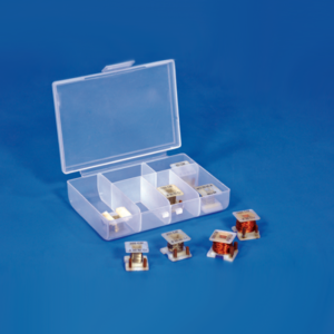
Resistance Coils

Unsymmetrical Bending Apparatus
DESCRIPTION:
Apparatus consist of an angle of size 1” x 1” x 1/8” or in equivalent metric units of length 80cm is tied as a cantilever beam. The beam is fixed at one end such that the rotation of 450 intervals can be given and clamped such that the principal axis of its cross-section may be inclined at any angle with the horizontal and vertical planes. Also arrangement is provided to apply vertical load at the free end of the cantilever and to measure horizontal and vertical deflection of the free end. A dial gauge with magnetic base is supplied with the apparatus.EXPERIMENT MANUAL:
• To study the behavior of a cantilever beam under symmetrical and unsymmetrical bending. • Using a Dial gauge shown a increasing and decreasing of heights.

Ripple Tank
Description :-
Transparent acrylic plastic ripple tank, supported in a sturdy plastic frame which has recesses to hold four legs with leveling feet.
The tank edges are shaped to minimize undesired reflections.
Tank has a drain hole closed by a rubber stopper.
With two light alloy uprights to carry a horizontal rippler support rod which is adjustable for height.
The ripple assembly, elastically suspended from the support rod, consists of a 4 – 6 V DC motor mounted on a wooden beam.
The motor has an eccentric weight which causes the beam to oscillate.
Two point sources are provided by two plastic spheres, each mounted on a right angle rod.
A metal rod is fixed centrally into a socket in one short side of the frame to afford support to the illuminant.
Overall size of the tank 580 x 500 x 80 mm, window area 370 x 280 mm, height of tank above bench level (with legs attached) approx. 375 mm.
Complete with following accessories :-
1. Two straight obstacles of aluminium alloy length 130 mm.
2. One straight obstacle length 40 mm.
3. One curved reflector radius 200 mm.
4. One trapezoidal plastic plate for refraction.
5. One wood hand wave roller.
6. One water dropper.
7. One pkt. rubber bands.
8. One foam plastic sponge.
9.One illuminant with a 12 V, 24 W lamp mounted in a lamp house and provided with a long supporting rod.
XTEMOS ELEMENT
AJAX PRODUCTS TABS WITH ICONS

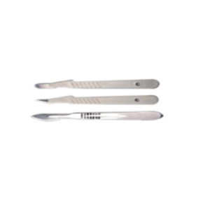
Surface Tension Balance, Searle’s
A horizontal frame is mounted on a rod fitted to a base & carries a steel wire stretched across it, the tension of which can be adjusted by a tightening screw.
A light metal pointer with a counterpoise is attached to the centre of the wire clamp.
A pan is hung from a notch in the pointer and has a hook at its underside from which can be suspended a light weight rectangular frame or a metal clip to hold a micro slide edge.
The tip of the pointer moves over a graduated scale. With rectangular wire frame, slide clip, six micro slides & 3 meters of spare wire.
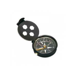
Pocket Compass
XTEMOS ELEMENT
AJAX PRODUCTS TABS LOAD MORE PAGINATION
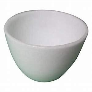
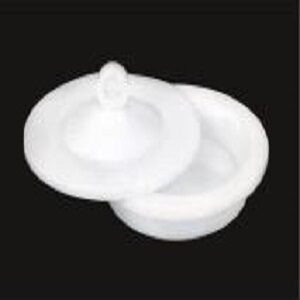
SILICA CRUCIBLE WITHOUT LID
PRODUCT DESCRIPTION
- Crucible is glazed inside and outside.
- Highly resistant to alkalis and hot temperatures
- 50ml capacity
- Outside diameter 55mm, 42mm height
- No lid includedSilica crucible is glazed inside and outside. Highly resistant to alkalis and hot temperature SIZES ARE: 15ML 25ML 50ML 80ML 100ML 150ML

SILICA CRUCIBLE TALL FORM Without Lid, Translucent

XTEMOS ELEMENT
AJAX PRODUCTS TABS CAROUSEL

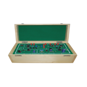
SCR VI Characteristics Study Trainer
Specification
• Basic VI characteristics study trainer. • Consists of one no. TYN612 SCR with heat sink. • LM723 based 20V DC power supply for gate voltage. • One no. potentiometer used to vary the gate current • 0- 30V DC variable power supply for anode, cathode voltage variation. • One no. potentiometer used to vary the Vak. • One no. high voltage fixed load resistor. • One no. toggle switch to ON/OFF gate voltage. • Two nos. DC ammeter, voltmeter/multimeter provided to measure Ig&Vak, Ia. • 230V AC input. Power ON/OFF switch. • All components are mounted on a screen printed PCB fixed on a nice wooden cabinets.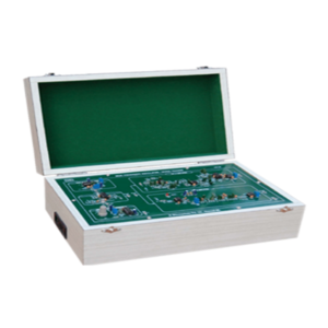
Beat Frequency Oscillator Trainer
FEATURES:
• On board sine generator • Transistor based mixer • Built in power supply • Easy interconnections are made by patch chords • Detailed documentationTECHNICAL SPECIFICATIONS:
• Sine Source - Fixed Frequency : 43.5 KHz - Variable Frequency : 41 KHz to 45 KHz • Transistor based mixer provided • Built-in amplifier • Power supply - + 12V DC, 200 mA - Unit is operated using 230V AC Power.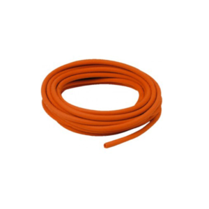
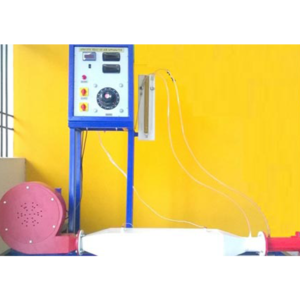
Specific Heat Of Air Apparatus
The apparatus consists of heating element on which the air is blown. The difference in temperature of air is shown by the temperature indicator. The flow of air is measured by the orifice meter. The input to the heater is measured by voltmeter and ammeter. Thus the specific heat of air can be found out.
SPECIFICATIONS:
1.Air blower connected to FHP motor. 2.Orifice meter to measure the air flow, Heater – 1 KW heating coil placed centrally in the test section. 3.Multi channel digital temperature indicator – range 0 to 300 c. 4.Voltmeter and ammeter to measure the heat Input.SERVICES REQUIRED:
1.220 volts single phase stabilized AC Electric supply. 2.Floor space – 2 m. X 1 m. X 2 m. Height.