XTEMOS ELEMENT
AJAX PRODUCTS TABS
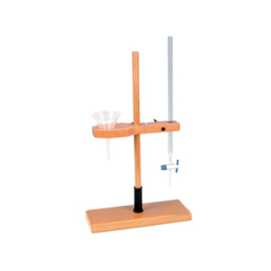
Funnel and Burette Combined Stand, Polished Wood
Episiotomy Training Simulator
Description
Suturing Simulators provide a realistic way for students to learn good surgical techniques. The simulators provide students with a variety of repair experiences without the constraint of time and concern for safety, which are factors with a live patient. The simulators can be used by the student in a learning lab with an instructor or by the student individually in the clinical setting just prior to a patient experience. They are also useful as homework teaching aids that can be signed out at night and returned the next day. In addition to being portable, the lifelike texture allows the learner to develop a “feel” for instrument handling, tension on suture, and the advantages of one method of tying knots over another.Includes one of each simulator:
Midline Suture Simulator Left Mediolateral Suture Simulator Right Mediolateral Suture Simulator Each simulator comes with an instruction booklet and is individually boxed.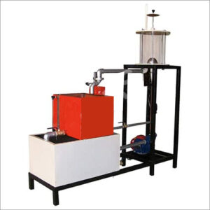
Impact Of Jet On Vanes Apparatus
DESCRIPTION:-
The Set-up consists of two sided clear fabrication. Water is fed through a nozzle and discharged vertically to strike a target carried on a stem, which extends through the cover. A weight carrier is mounted on the upper end of the stem. The dead weight of the moving parts is counter balanced by a compression spring. The vertical force exerted on the target plate is measured by adding the weights supplied to the weight pan until the mark on the weight pan corresponds with the level gauge. A total of two targets are provided a flat plat and a hemispherical cup.EXPERIMENTS:-
Ø To measure the force developed by a jet of water impinging upon a different targets (Hemispherical & Flat Plate) and comparison with the forces predicted by the momentum theory.UTILITIES REQUIRED: –
Ø Water Supply & Drain Ø Electricity Supply: Single Phase, 220 VAC, 0.5 kWTECHNICAL SPECIFICATION: –
Ø Test Plates : Material Brass (2 Nos.) 1. Flat Plate 2. Hemispherical Cup Ø Nozzle : Material Brass Ø Stainless Steel Chamber : Having of opposite sides made of glass Ø Water Circulation : FHP Pump, Crompton / Sharp make Ø Flow Measurement : Using Measuring Tank with Piezometer,Capacity 40 Ltrs. Ø Sump Tank : Capacity 60 Ltrs. Ø Stop Watch : Electronic Ø Control Panel : On / Off Switch, Mains Indicator etc. Ø The whole Set-up is well designed and arranged in a good quality painted Structure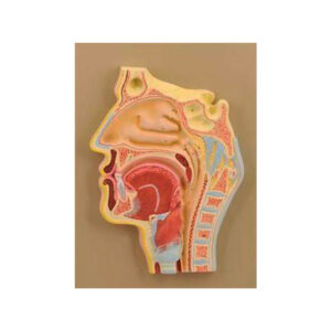
Human Nose, L. S.
XTEMOS ELEMENT
AJAX PRODUCTS TABS SIMPLE

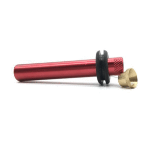

Burner Bunsen – Simple, LPG
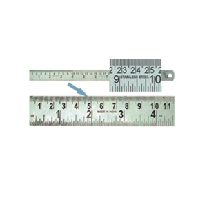
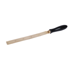
Rules Steel
XTEMOS ELEMENT
AJAX PRODUCTS TABS ALTERNATIVE
Fashion

Electric Motor, Demonstration
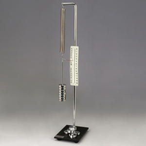
Hook’s Law Apparatus
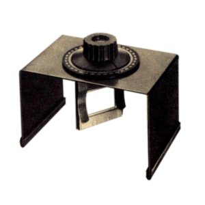
Refractive Index of Water Apparatus
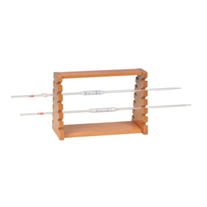
Pipette Stand, Wooden – Horizontal
XTEMOS ELEMENT
AJAX PRODUCTS TABS ARROWS PAGINATION
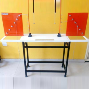
Portal Frame Apparatus
DESCRIPTION:
Portal Frames used for the measurement of horizontal reaction are made stiffer by using M. S. flats rectangular cross section (10mm thick and 40mm wide). All are true to shape. The ends can be other fixed of hinged as desired. The end at which horizontal reaction, is to be measured, is provided with ball bearing rollers, which easily rolls on a smooth rolling platform. At the roller end a chord is attached which is connected further to spring balance. The spring balance records the horizontal reaction, for the measurement of slope and deflection. Both the columns of the portal frame can be clamped (fixed) or pivoted (hinged) and required.EXPERIMENT:
• To study the behavior of a portal frame under different end conditions.TECHNICAL SPECIFICATION:
• Apparatus made up of M.S. plate of rectangular section of 3mm thick x 40cm wide. • Frame is provided with a provision to achieve different end conditions viz. hinged, roller & fixed. • The size of portal will be 40cm x 60cm. Portal may also have a provision for pulley arrangement and hook arrangement for horizontal loading at different positions. • Apparatus is to be supplied complete with a supporting stand and a set of weights • Electronic load cells, displacement cell and Electronic Control Unit (ECU) provided with apparatus. • Software for digital calculations to easily performs by students.OPTIONAL ACCESSORIES:
• PC/Laptop Set.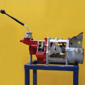
Synchromesh Gear Box 4 Forward 1reverse
Synchromesh Gear Box – 4 Forward & 1Reverse Actual Cut Section
The working of gear box is shown with the help of actual parts assembled on square iron pipe frame. All the necessary parts of gear box are shown in actual working form. This model helps the student to understand the working of the gear box very easily. It is specially made dissectible for demonstration purposes.
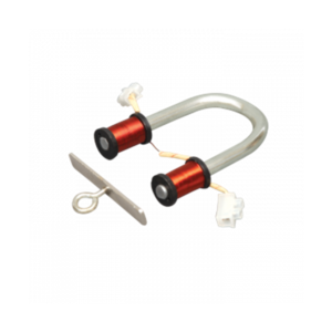
Electromagnet
XTEMOS ELEMENT
AJAX PRODUCTS TABS WITH ICONS
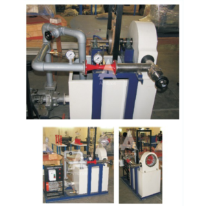
Pelton Wheel Turbine Test Setup
DESCRIPTION:
Pelton Wheel Turbine is only impulse water turbine now in common use named in honor of Sir L.A. Pelton (1829-1908) of California, USA. It is a tangential flow impulse turbine. The water strikes the buckets along the tangent of the runner. The energy available at the Inlet of the Turbine is only kinetic energy. The Pressure at the Inlet and Outlet of the atmospheric. This turbine is used for high heads. The Present Set-up consists of a runner. The buckets are mounted on the runner. The water is fed to the turbine, through SS nozzle with a SS spear, by means of Centrifugal Pump, tangentially to the runner. Row of water into turbine is regulated by adjusting the spear position by the help of a given hand wheel the runner is directly mounted on one end of a central SS shaft and other end is connected to a brake arrangement. The circular window of the turbine casing is providing with a transparent acrylic sheet for observation of flow on to the buckets. This runner assembly is supported by rigid MS structure. Load is applied to the turbine with the help of this brake dynamometer so that the efficiency of the turbine can be calculated. Pressure Gauge is fitted at the Inlet of the turbine to measure the total supply head to the turbine.EXPERIMENT:
1.To study the operation of a Pelton Wheel Turbine 2.To determine the Output Power of Pelton Wheel Turbine 3.To determine the Turbine EfficiencyUTILITIES REQUIRED:
● Water Supply and Drain.● Electricity 15 kW, 440V AC, Three Phase
TECHNICAL SPECIFICATIONS:
| MODEL | HM 111 (1.33 HP) | HM 111 (2 HP) | HM 111 (5 HP) |
| Output Power | 1.33 HP / 1 Kw | 2 HP / 1.5 Kw | 5 HP / 3.75 Kw |
| Discharge | 300 LPM (Approx.) | 400 LPM (Approx.) | 630 LPM (Approx.) |
| Supply Head | 25 m | 40 m | 45 m |
| Rope Brake Dynamometer | Dia 200 mm | Dia 200 mm | Dia 300 mm |
| Sump Tank | Capacity 150 Liters. | Capacity 200 Liters. | Capacity 300 Liters. |
| Water Circulation Centrifugal Pump | Capacity 5 HP, Three Phase | Capacity 7.5 HP, Three Phase | Capacity 15 HP, Three Phase |
| Speed | 1000 RPM (approx.) | ||
| Impeller | Material Brass, Bucket type | ||
| Nozzle | Material Stainless Steel/Mild Steel | ||
| Spear | Material Stainless Steel/Mild Steel | ||
| Discharge Measurement | Pitot Tube with Manometer | ||
| Control Panel | Star/Delta Starter, Mains Indicator, MCB for overload protection | ||
| The whole set-up is well designed and arranged in a good quality painted structure. | |||
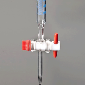

Bell In Bell Jar

Oxygen And Carbon Cycle In Nature
XTEMOS ELEMENT
AJAX PRODUCTS TABS LOAD MORE PAGINATION
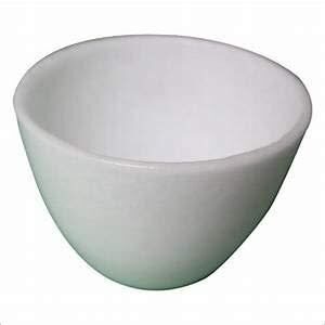
SILICA CRUCIBLE WITHOUT LID
PRODUCT DESCRIPTION
- Crucible is glazed inside and outside.
- Highly resistant to alkalis and hot temperatures
- 50ml capacity
- Outside diameter 55mm, 42mm height
- No lid includedSilica crucible is glazed inside and outside. Highly resistant to alkalis and hot temperature SIZES ARE: 15ML 25ML 50ML 80ML 100ML 150ML
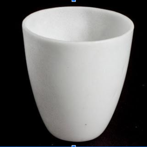
SILICA CRUCIBLE TALL FORM Without Lid, Translucent
XTEMOS ELEMENT
AJAX PRODUCTS TABS CAROUSEL
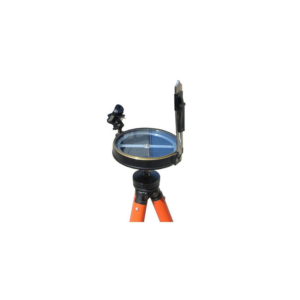
Survey Compass
Description
• Compass survey is a method of surveying by taking bearings and linear distances to produce plan. • Bearing is measured using prismatic compass, while the linear distance is measured using measuring tape. • Bearing in compass surveying means angle is made by chain line or survey line by referring it to magnetic meridian or magnetic north.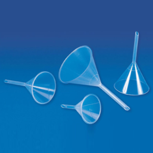
Long Stem Funnel
We offer Long Stem Funnel which is made in accordance to the international standards.
These Long Stem Funnel have smooth walls, 60" cone angle and external ribs to prevent air lock.
Moulded in Polypropylene, these clear funnels can also be steam autoclaved.
Material : Polypropylene
| Particulars | Pack (Pcs) | |
|---|---|---|
| Funnel- Long Stem 100 mm | 36 | |
| Funnel- Long Stem 150 mm | 12 | |
| Industrial Funnel 200 mm | 12 | |
| Industrial Funnel 250 mm | 6 |